
Superheated urea injection for aftertreatment applications

a technology of aftertreatment and urea injection, which is applied in the direction of machines/engines, mechanical equipment, separation processes, etc., can solve the problems of low temperature operation of adsorbers, the inability of combustion optimization alone to meet and the inability to achieve the epa proposed levels for the future. , to achieve the effect of enhancing internal combustion engine aftertreatment applications

Inactive Publication Date: 2007-05-31
FLEETGUARD INC
View PDF9 Cites 37 Cited by
  • Summary
  • Abstract
  • Description
  • Claims
  • Application Information

AI Technical Summary

Benefits of technology

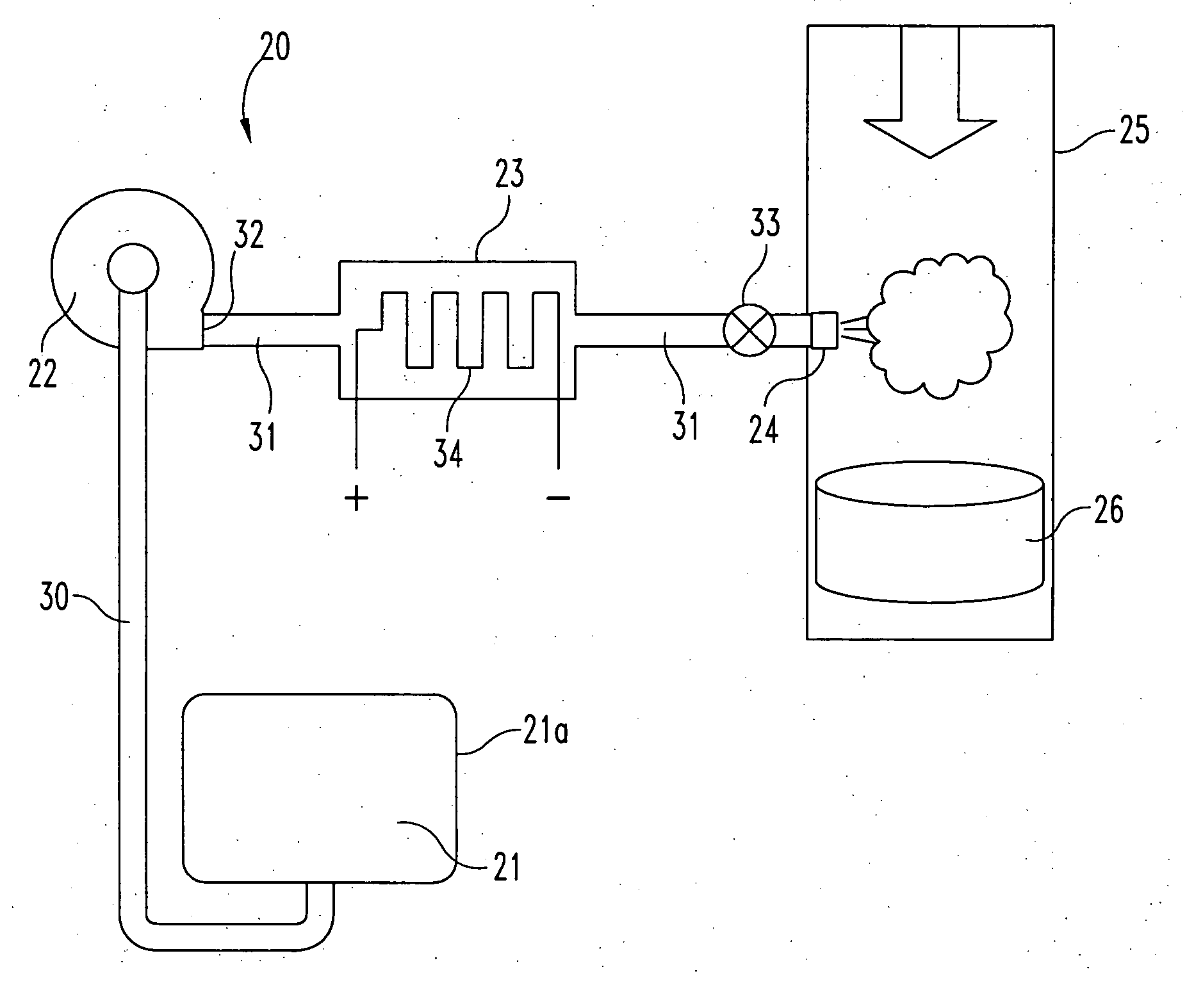
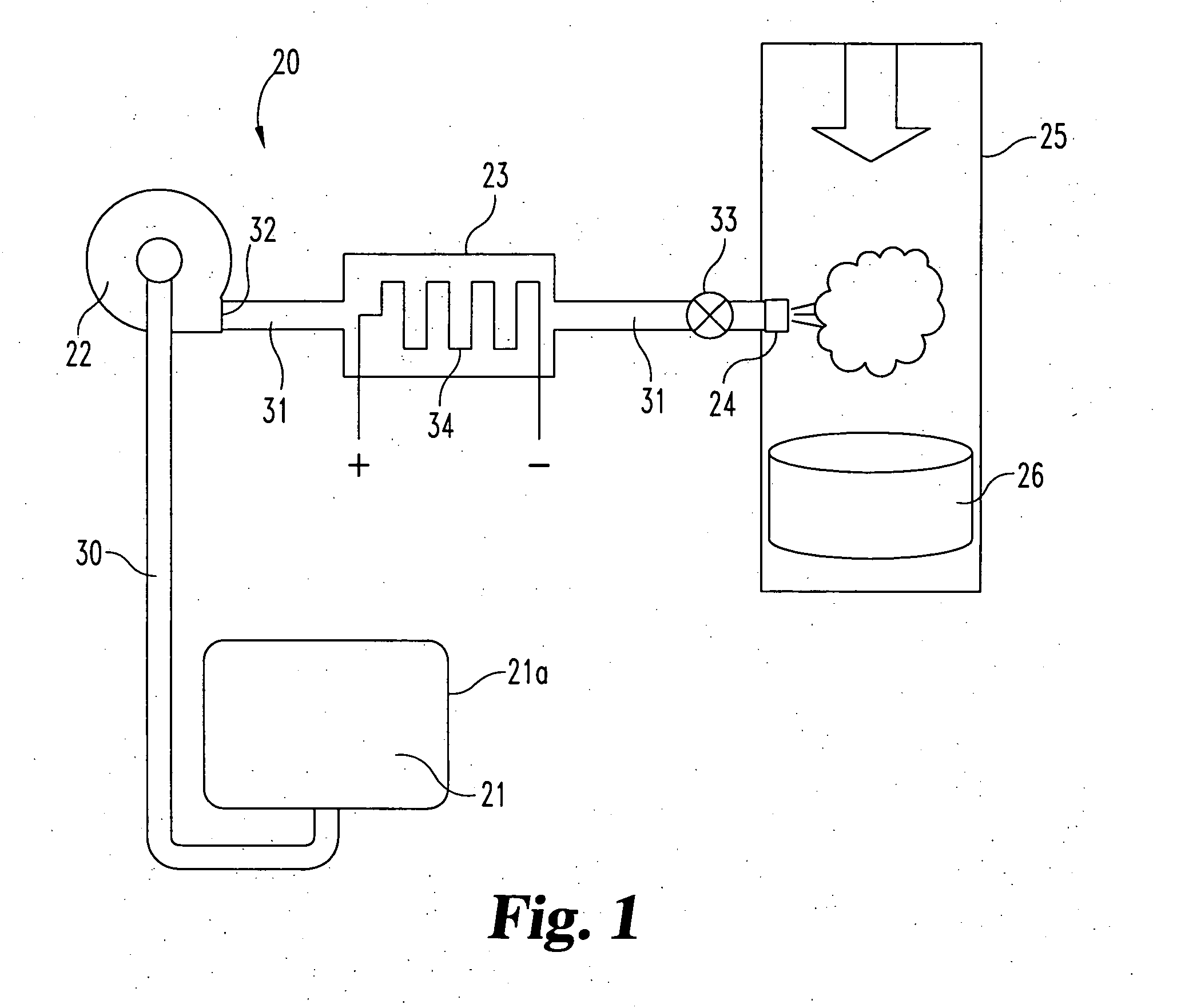
[0011] An urea SCR system for enhancing internal combustion engine aftertreatment applications according to one embodiment of the present invention comprises a supply of urea solution, a delivery pump for delivering urea solution into an exhaust stream at an injection location, and a heating device positioned between the supply of urea solution and the injection location for preheating the urea solution prior to injection into the exhaust stream.

Problems solved by technology

Reducing NOx (NO and NO2) emission in diesel exhaust gas has been a major challenge during the past several years and will continue to be a major focus in the future due to the continuing stringent emission requirements for diesel engines.
While these two approaches remain compatible, combustion optimization has NOx reduction limits and alone will likely not be able to meet the EPA proposed levels for the future, such as the U.S. 2007 heavy-duty diesel emission standard.
However, low temperature operation of adsorbers seems to be a problem.
Also, if the droplet size is large, atomization is not good and the fuel does not vaporize easily even at the higher temperature, thereby limiting adsorber performance.
Current devices on their own, such as spraying system nozzles and injectors cannot do anything about the condensation at low temperature.
While this approach offers one option for NOx reduction, it does not provide a urea-based system.

Method used


Image

  • Superheated urea injection for aftertreatment applications
  • Superheated urea injection for aftertreatment applications

Examples


Embodiment Construction

[0015] For the purposes of promoting an understanding of the principles of the invention, reference will now be made to the embodiments illustrated in the drawings and specific language will be used to describe the same. It will nevertheless be understood that no limitation of the scope of the invention is thereby intended, such alterations and further modifications in the illustrated device, and such further applications of the principles of the invention as illustrated therein being contemplated as would normally occur to one skilled in the art to which the invention relates.

[0016] Referring to FIG. 1, there is illustrated an urea SCR system for enhancing internal combustion engine aftertreatment applications. Urea SCR system 20 includes a supply 21 of aqueous urea, a pressurizing delivery pump 22, a heating location or station 23, and a valve-controlled injection nozzle 24. Also illustrated in FIG. 1 is an exhaust conduit 25 of a diesel engine (not illustrated) and a selective c...


PUM

PropertyMeasurementUnit
temperaturesaaaaaaaaaa
sauter mean diameteraaaaaaaaaa
pressureaaaaaaaaaa

Abstract

An urea SCR system for enhancing internal combustion engine aftertreatment applications includes a supply tank containing aqueous urea, a delivery pump operatively connected to the supply tank and configured for elevating the pressure of aqueous urea drawn from said supply tank. The urea SCR system further includes a conduit arrangement connecting the delivery pump to an injection nozzle which is positioned adjacent an exhaust stream, the conduit arrangement being configured for the delivery of aqueous urea to the injection nozzle. Downstream of the delivery pump and upstream from the injection nozzle, a heating element is positioned for preheating of the aqueous urea to a superheated condition prior to injection into the exhaust stream.

Description

BACKGROUND OF THE INVENTION [0001] The present invention relates in general to internal combustion engine technology and to reducing the level of NOx emission by selected catalytic reduction (SCR). More specifically, the present invention relates to the use of urea injection upstream from the SCR site, in the vehicle exhaust stream, as part of an urea SCR exhaust aftertreatment system and approach for a diesel engine. [0002] Reducing NOx (NO and NO2) emission in diesel exhaust gas has been a major challenge during the past several years and will continue to be a major focus in the future due to the continuing stringent emission requirements for diesel engines. Engine exhaust NOx reduction can be achieved in part by more optimal or more complete combustion and in part by exhaust gas aftertreatment. While these two approaches remain compatible, combustion optimization has NOx reduction limits and alone will likely not be able to meet the EPA proposed levels for the future, such as the...

Claims


Application Information

Patent Timeline
Patent Type & Authority Applications(United States)
IPC IPC(8): F01N3/00
CPCB01D53/90B01D53/9431B01D2251/2067F01N3/2066F01N2390/00F01N2610/02F01N2610/10Y02T10/24Y02T10/12
Inventor PIERZ, PATRICK M.TIKK, LASZLO D.
Owner FLEETGUARD INC
Learn More