
Cassette and mechanical arm and process apparutus

a technology of mechanical arm and process apparatus, which is applied in the direction of electrical apparatus, rolling carts, basic electric elements, etc., can solve the problems of mechanical arm poisoning and damage to electronic devices on the substrate, and achieve the effect of improving the deformation of the side-bearing arms and the substra

Inactive Publication Date: 2007-05-24
CHUNGHWA PICTURE TUBES LTD
View PDF13 Cites 7 Cited by
  • Summary
  • Abstract
  • Description
  • Claims
  • Application Information

AI Technical Summary

Benefits of technology

[0009] In view of this, one object of the present invention is to provide a cassette for improving the deformation of the side-bearing arms and the substrates in the traditional cassette.
[0010] Another object of the present invention is to provide a mechanical arm for improving the difficulties in the positioning of the traditional mechanical arm.
[0011] One another object of the present invention is to provide a process apparatus for improving the damages of the electronic devices on the substrate caused by the electro-static discharge.
[0024] Based on the descriptions above, because the cassette according to the present invention utilizes the conveying unit composed of the rollers and magnetic lead pole for bearing and conveying the substrates, the deformation of the substrates can be improved, and the difficulties in positioning of the mechanical arm can be decreased. Besides, according to the present invention, the designing of the loading / unloading chamber of the process apparatus can be simplified, and the damages of electronic devices caused by electro-static discharge can be avoided.

Problems solved by technology

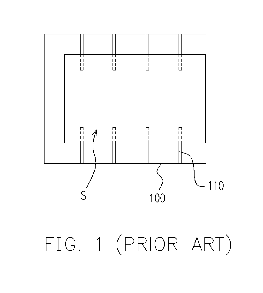
It's worthy to note that the aforementioned bearing pins 212 used for bearing the substrate S needs to be designed properly, allowing the mechanical arm 120 to move in or out the substrate S. However, an improper design of the locations of the bearing pins 212 causes the difficulties in the poisoning of the mechanical arm 120.
Furthermore, when the bearing pins 212 get in touch with the substrate S, the electro-static discharge may appear between them, thereby damaging the electronic devices on the substrate S.

Method used


Image

  • Cassette and mechanical arm and process apparutus
  • Cassette and mechanical arm and process apparutus
  • Cassette and mechanical arm and process apparutus

Examples


Embodiment Construction

[0033]FIGS. 4A and 4B schematically show a top view and a side view of a cassette according to an embodiment of the present invention, respectively. Referring to FIGS. 4A and 4B, in a semiconductor process, a substrate S to be processed or processed already can be placed in a cassette 300 shown in FIG. 4A. This cassette 300 includes a case 310 and a conveying unit 320. The conveying unit 320 is located in the case 310 and it can be used for bearing one substrate S. It is easily understood that the cassette 300 for the present embodiment can include a plurality of conveying units for bearing a plurality of substrates S, as shown in FIG. 4B. Nevertheless, the cassette 300 with one conveying unit 320 of the embodiment herein is illustrated for simplicity

[0034] In the present embodiment, the conveying unit 320 includes a plurality of rollers 322 and a plurality of magnetic lead poles 324 wherein these rollers 322 are disposed in parallel for bearing the substrate S. In addition, each o...


PUM


Abstract

A cassette suitable for placing at least one substrate provided. The cassette includes a case and at least a conveying unit. The conveying unit is disposed inside the case and comprises a plurality of rollers for bearing the substrate and at least a magnetic lead pole. Wherein, the magnetic lead pole is electrically connected to one of the rollers, and rotation of a corresponding roller is driven to move the substrate when the magnetic lead pole rotates. In addition, the present invention also discloses a mechanical arm and a process apparatus.

Description

BACKGROUND OF THE INVENTION [0001] 1. Field of Invention [0002] The present invention relates to a cassette, a mechanical arm and a process apparatus. More particularly, the present invention relates to a cassette, a mechanical arm and a process apparatus that utilize the magnetic lead poles. [0003] 2. Description of Related Art [0004] The thin film transistor liquid crystal display (TFT-LCD) plays an important role in the display marketplace nowadays, and it mainly comprises a liquid crystal display (LCD) panel, a back light module. The LCD panel is mainly composed of a color filter (CF) substrate, a thin film transistor (TFT) array substrate and a liquid crystal (LC) layer disposed between the CF substrate and the TFT array substrate. Here, the TFT array substrate is manufactured by performing multiple fabricating processes to form a plurality of thin film transistors (TFTs) arranged in matrix on the glass substrate for driving the LC layer. [0005]FIG. 1 schematically shows a trad...

Claims


Application Information

Patent Timeline
IPC IPC(8): B65G13/02
CPCB65G49/064B65G49/067B65G49/068B65G2249/02H01L21/67709H01L21/67721H01L21/67778
Inventor LIU, TA-YU
Owner CHUNGHWA PICTURE TUBES LTD
Learn More