
Moving image display device and method for moving image display

a technology of moving image and display device, which is applied in the direction of television system, color signal processing circuit, instruments, etc., can solve the problems of flicker (blinking) on the overall screen, flicker only in the moving object part, and felt stress while viewing, so as to prevent flicker and smooth display of moving image

Inactive Publication Date: 2007-05-10
SEIKO EPSON CORP
View PDF12 Cites 30 Cited by
  • Summary
  • Abstract
  • Description
  • Claims
  • Application Information

AI Technical Summary

Benefits of technology

[0010] One aspect of the present invention aims to provide a simpler technique than the prior art technique to prevent flicker in a moving image and ensure smooth display of the moving image.
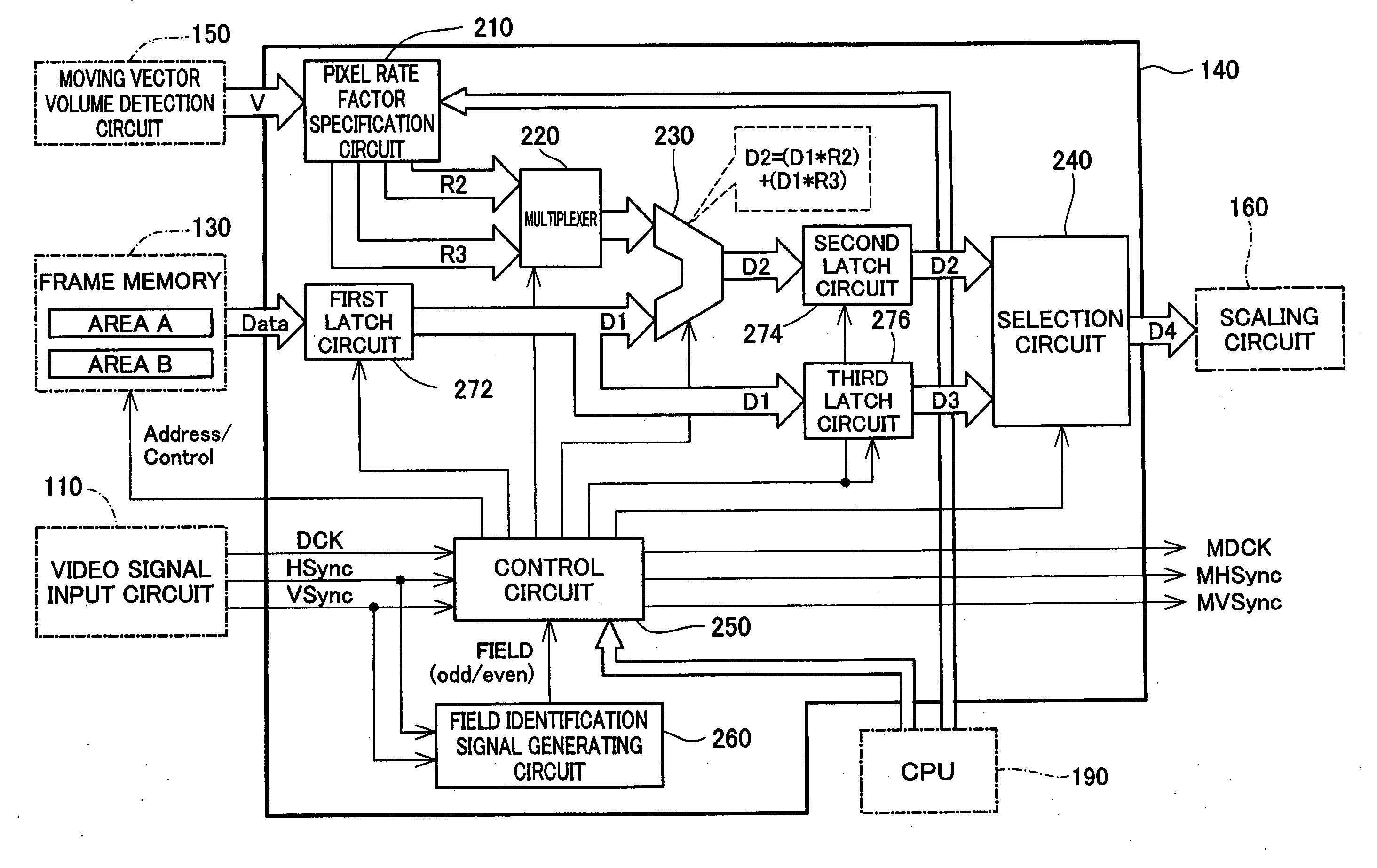
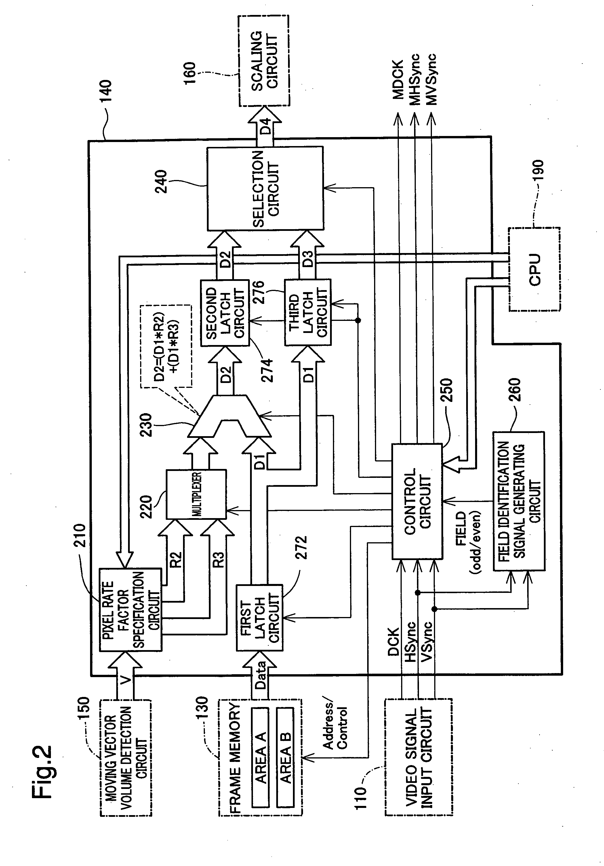
[0012] The moving image display device of the invention adopts the extremely simple process for generation of the intermediate frame image and thus desirably enhances the processing speed. The simple process adjusts the mixing rates of the first frame image and the second frame image, which are to be displayed in this sequence, extracts the pixels from the first frame image and from the second frame image in a complementary manner, and combines the extracted pixels to generate the intermediate frame image. The synthesis process can readily follow the higher frame rate increased from the frame rate of the original moving image. This arrangement effectively prevents flicker in a moving image and ensures smooth display of the moving image.
[0013] The moving image display device of the invention adjusts the mixing rates of the first frame image and the second frame image, which are to be displayed in this sequence, extracts the pixels from the first frame image and from the second frame image in a complementary manner, and combines the extracted pixels to readily generate the intermediate frame image. Adoption of this extremely simple synthesis technique does not require generation of completely new intermediate frame images. The synthesis process accordingly has the extremely simple hardware configuration and saves the required memory capacity. This arrangement desirably reduces the manufacturing cost and still provides a moving image display device having the capability of smooth video display.

Problems solved by technology

In the past, when displaying images on a moving image display device such as a CRT, television or the like with a refresh rate of less than 60 Hz, there were cases when flicker (blinking) occurred on the overall screen.
However, even when a sufficient refresh rate is secured, in cases when displaying moving images such as when a moving object moves on the screen, there were cases when flicker occurred only in the moving object part on the screen rather than on the overall screen.
This kind of phenomenon is not limited to CRTs and televisions, but is also seen in cases when displaying moving images on moving image display devices such as liquid crystal displays, plasma displays, projectors or the like, on the display unit of a PDA, mobile phone or the like, or on the screen in a movie theater or the like, and this was a problem common to moving image display.
There were cases when once the viewers became bothered by the existence of the moving image flicker described above, they felt stress while viewing.
However, with the prior art described above, because it is necessary to generate a completely new intermediate frame from two frame images, the calculation processing for this becomes huge, so it was difficult to improve the moving image display speed.
Also, to generate a completely new intermediate frame, it is necessary to secure a large frame memory capacity, and this became a factor in increasing costs.
Also, when switching the display method with moving images and still images, there was concern that smooth video image display would not be possible due to the occurrence of a virtual image during switching of the display method or the like.

Method used


Image

  • Moving image display device and method for moving image display
  • Moving image display device and method for moving image display
  • Moving image display device and method for moving image display

Examples


first embodiment

[0037] A. First Embodiment [0038] (A-1) Hardware Configuration of Projector

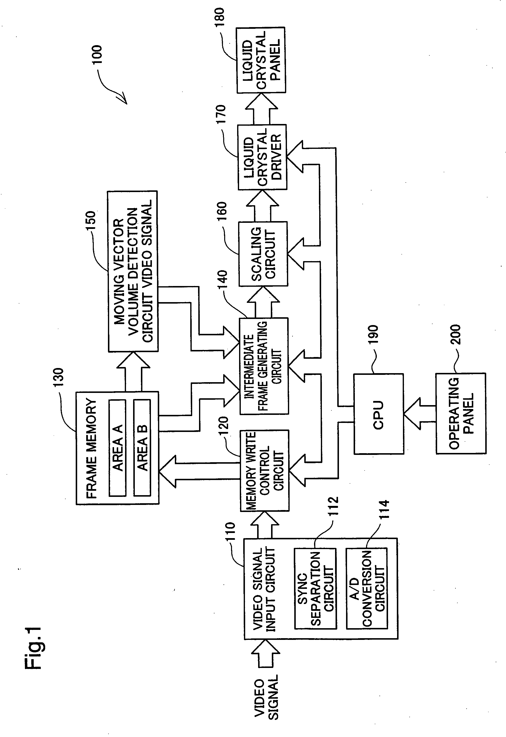
[0039]FIG. 1 is a block diagram showing the hardware configuration of a projector 100 in one embodiment of the moving image display device of the invention. The projector 100 has the function of displaying a moving image with at least a 2-fold frame rate of an original moving image. A concrete arrangement for enabling the video display with at least the 2-fold frame rate will be described later in detail.

[0040] As illustrated, the projector 100 of the embodiment includes a video signal input circuit 110, a memory write control circuit 120 connected with the video signal input circuit 110, a frame memory 130 connected with the memory write control circuit 120, a moving vector volume detection circuit 150 connected with the frame memory 130, an intermediate frame generating circuit 140 connected with the frame memory 130 and the moving vector volume detection circuit 150, a scaling circuit 160 connected with ...

second embodiment

[0077] B. Second Embodiment

[0078] The first embodiment described above generates one intermediate frame image between each pair of existing frame images and displays a moving image at the 2-fold cycle of the frame rate of the original moving image. A second embodiment described below generates two intermediate frame images between each pair of existing frame images and displays a moving image at a 3-fold cycle of the frame rate of the original moving image.

[0079]FIG. 7 shows visual representation of a moving image formed on the liquid crystal panel 180 in the second embodiment. As shown in the upper row and the middle row of FIG. 7, in the second embodiment, when the memory write control circuit 120 sequentially writes frame image data of frames (n−1), (n), and (n+1) into the frame memory 130, the control circuit 250 reads out the frame image data five consecutive times at a 3-fold cycle of the frame rate of the original moving image. Alternate output of corresponding pixels attain...

third embodiment

[0083] C. Third Embodiment

[0084] The second embodiment described above generates two intermediate frame image between each pair of existing frame images and displays a moving image at the 3-fold cycle of the frame rate of the original moving image. A third embodiment described below generates three intermediate frame images between each pair of existing frame images and displays a moving image at a 4-fold cycle of the frame rate of the original moving image.

[0085]FIG. 8 shows visual representation of a moving image formed on the liquid crystal panel 180 in the third embodiment. As shown in the upper row and the middle row of FIG. 8, in the third embodiment, when the memory write control circuit 120 sequentially writes frame image data of frames (n−1), (n), and (n+1) into the frame memory 130, the control circuit 250 reads out the frame image data seven consecutive times at a 4-fold cycle of the frame rate of the original moving image. Alternate output of corresponding pixels attain...


PUM


Abstract

In the moving image display device of the invention, a synthesis circuit inputs signals representing specified values of pixel rate factors R2 and R3 from a pixel rate factor specification circuit, while inputting overscanned frame image data D1 in the units of pixels from a 1st latch circuit. The synthesis circuit extracts a preset number of pixels corresponding to the specified value of the pixel rate factor R2 from a prior frame image, while extracting a preset number of pixels corresponding to the specified value of the pixel rate factor R3 from a latter frame image. The positions of pixels to be extracted from the latter frame image are complementary to the positions of pixels to be extracted from the prior frame image. The synthesis circuit combines the extracted pixels of the prior frame image with the extracted pixels of the latter frame image by a logical OR operation to generate intermediate frame image data D2. This technique of the invention is significantly simpler than the prior art technique but still effectively prevents flicker in a moving image to ensure smooth display of the moving image.

Description

CLAIM OF PRIORITY [0001] The present application claims priority from Japanese Patent Applications P2005-320597A filed on Nov. 4, 2005, the contents of which are hereby incorporated by reference into this application. BACKGROUND OF THE INVENTION. [0002] 1. Field of the Invention [0003] The present invention relates to technology for displaying moving images by consecutively displaying a plurality of frame images, and more specifically relates to technology for synthesizing a plurality of frame images and generating an intermediate frame image. [0004] 2. Description of the Related Art [0005] In the past, when displaying images on a moving image display device such as a CRT, television or the like with a refresh rate of less than 60 Hz, there were cases when flicker (blinking) occurred on the overall screen. However, even when a sufficient refresh rate is secured, in cases when displaying moving images such as when a moving object moves on the screen, there were cases when flicker occ...

Claims


Application Information

Patent Timeline
IPC IPC(8): H04N7/01G09G3/20G09G3/36G09G5/00G09G5/36H04N5/21H04N5/262
CPCG06T3/4007G09G3/001G09G3/3611G09G2320/0247G09G2340/10G09G2340/16H04N7/0132G09G3/20G09G5/00H04N5/14
Inventor TAKEUCHI, KESATOSHISAGAWA, TAKAHIROIISAKA, HIDEHITO
Owner SEIKO EPSON CORP
Learn More