
Determining camera motion

a three-dimensional imaging and camera technology, applied in the field of camera motion determination, can solve the problems of computational intensive techniques, additional difficulties in real imaging environments, and the inability to perform typical registration techniques such as the iterative closest point (“icp”) method with difficult-to-register surfaces, and achieve the effect of efficient parameterization

Active Publication Date: 2007-05-10
MEDIT CORP
View PDF6 Cites 168 Cited by
  • Summary
  • Abstract
  • Description
  • Claims
  • Application Information

AI Technical Summary

Benefits of technology

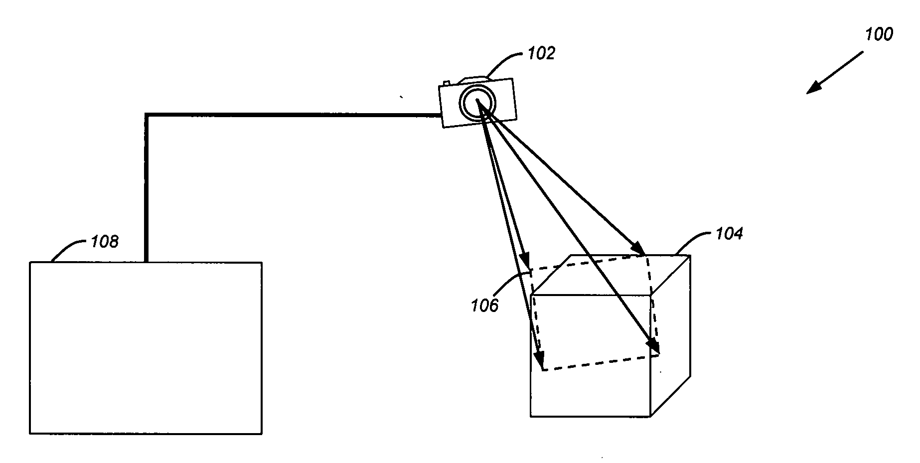
[0008] Camera motion is determined in a three-dimensional image capture system using a combination of two-dimensional image data and three-dimensional point cloud data available from a stereoscopic, multi-aperture, or similar camera system. More specifically, a rigid transformation of point cloud data between two three-dimensional point clouds may be more efficiently parameterized using point correspondence established between two-dimensional pixels in source images for the three-dimensional point clouds.

Problems solved by technology

One general technique for capturing three-dimensional data reconstructs an aggregate three-dimensional point cloud using sequential images from a moving camera, which raises the complementary problem of determining camera motion from image to image.
However, this technique is computationally intensive because point correspondence must be maintained over a number of sequential images.
This raises additional difficulties in real imaging environments where particular points may be obstructed, or fall entirely out of the image plane.
However, typical registration techniques such as the iterative closest point (“ICP”) method do not perform well with difficult-to-register surfaces, such as planar regions.
Further, iterative solutions are, in general, poorly suited to real-time imaging applications due to the requirement for multiple, successive calculations, frequently with large data sets.

Method used


Image

  • Determining camera motion
  • Determining camera motion
  • Determining camera motion

Examples


Embodiment Construction

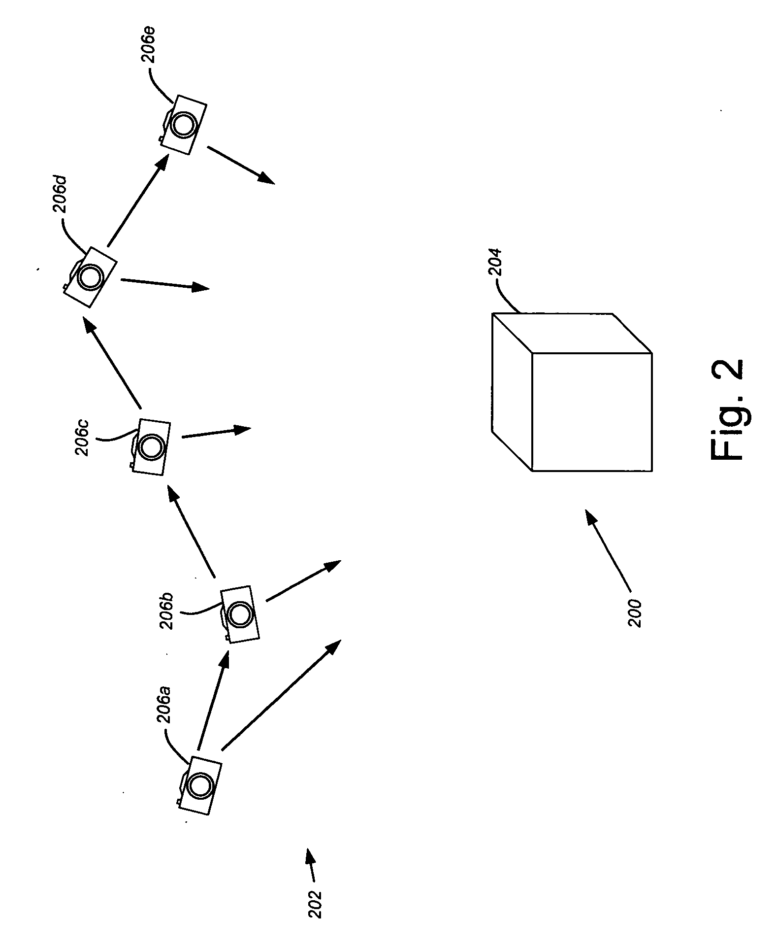
[0030] Described below is a technique for reconstructing an aggregate three-dimensional point cloud using camera motion determinations for a series of images from a stereoscopic or multi-aperture camera system. However, it will be appreciated that the inventive concepts disclosed herein are not limited to such applications, and may be usefully employed in any imaging system, for visible light or otherwise, in which two-dimensional and three-dimensional image data is available for use in reconstruction. Thus the techniques may be employed, for example, with a multi-camera motion picture system, a stereoscopic microscope, or any other imaging system where three-dimensional data might be derived from two-dimensional images. Similarly, while the following discussion focuses on a camera that moves relative to an imaging subject, the techniques described herein are equally applicable to a stationery camera that captures sequential images of one or more moving objects. In such uses, the an...


PUM


Abstract

Camera motion is determined in a three-dimensional image capture system using a combination of two-dimensional image data and three-dimensional point cloud data available from a stereoscopic, multi-aperture, or similar camera system. More specifically, a rigid transformation of point cloud data between two three-dimensional point clouds may be more efficiently parameterized using point correspondence established between two-dimensional pixels in source images for the three-dimensional point clouds.

Description

BACKGROUND [0001] 1. Field of the Invention [0002] This invention relates to determination of camera motion, and more particularly to determination of camera motion in a three-dimensional imaging system. [0003] 2. Description of the Related Art [0004] Three-dimensional image capture has long held promise as a data acquisition technique for a wide range of modeling systems including computer-aided design systems, digital animation systems, medical imaging systems, graphical design and artwork systems, and the like. [0005] One general technique for capturing three-dimensional data reconstructs an aggregate three-dimensional point cloud using sequential images from a moving camera, which raises the complementary problem of determining camera motion from image to image. A common approach to recovery of camera motion for these image sequences employs factorization on established point correspondences between two-dimensional images. However, this technique is computationally intensive bec...

Claims


Application Information

Patent Timeline
IPC IPC(8): G06T15/00
CPCG06T7/2033G06T7/2086G06T7/246G06T7/285
Inventor ZHANG, TONGROHALY, JANOSWEEKS, STEVEN V.
Owner MEDIT CORP
Learn More