
Apparatus and method for image guided insertion and removal of a cannula or needle

a technology of cannula and needle, applied in the field of magnetic system, can solve problems such as serious complications or even death, and the vascular wall is damaged

Inactive Publication Date: 2007-05-03
VERATHON
View PDF12 Cites 60 Cited by
  • Summary
  • Abstract
  • Description
  • Claims
  • Application Information

AI Technical Summary

Benefits of technology

The invention is a magnetic system that helps position a needle or cannula in a patient's body for medical purposes. It allows the needle to be held in place and moved around in one direction only. This makes it easier to insert the needle into a blood vessel or other body cavity and release it once the placement is confirmed. The system uses a special holding device that restricts the movement of the needle, but allows it to slide along a certain line relatively freely. The force of the restricting force can be adjusted to allow for unrestricted separation of the needle and the holding device.

Problems solved by technology

Unsuccessful insertion and / or removal of a cannula, a needle, or other similar devices into vascular tissue may cause vascular wall damage that may lead to serious complications or even death.
The motion and force required to disengage the cannula from the guidance system may, however, contribute to a vessel wall injury, which may result in extravasation.

Method used


Image

  • Apparatus and method for image guided insertion and removal of a cannula or needle
  • Apparatus and method for image guided insertion and removal of a cannula or needle
  • Apparatus and method for image guided insertion and removal of a cannula or needle

Examples


Embodiment Construction

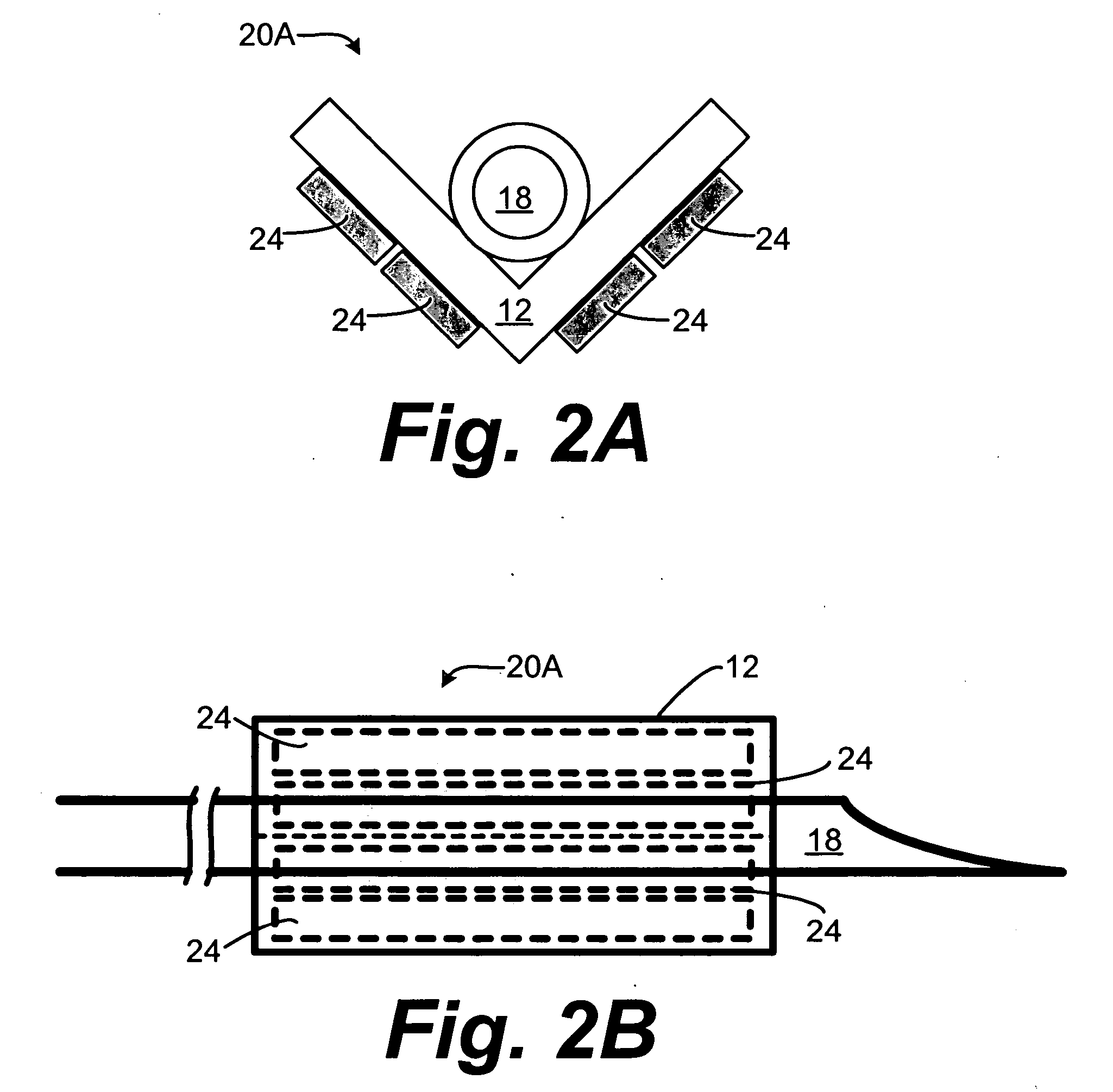
[0061] The present invention relates to an apparatus and a method for image guided insertion and removal of a cannula or needle. Many specific details of certain embodiments of the invention are set forth in the following description and in FIGS. 1 through 20B to provide a thorough understanding of such embodiments. One skilled in the art, however, will understand that the present invention may have additional embodiments, or that the present invention may be practiced without several of the details described in the following description.

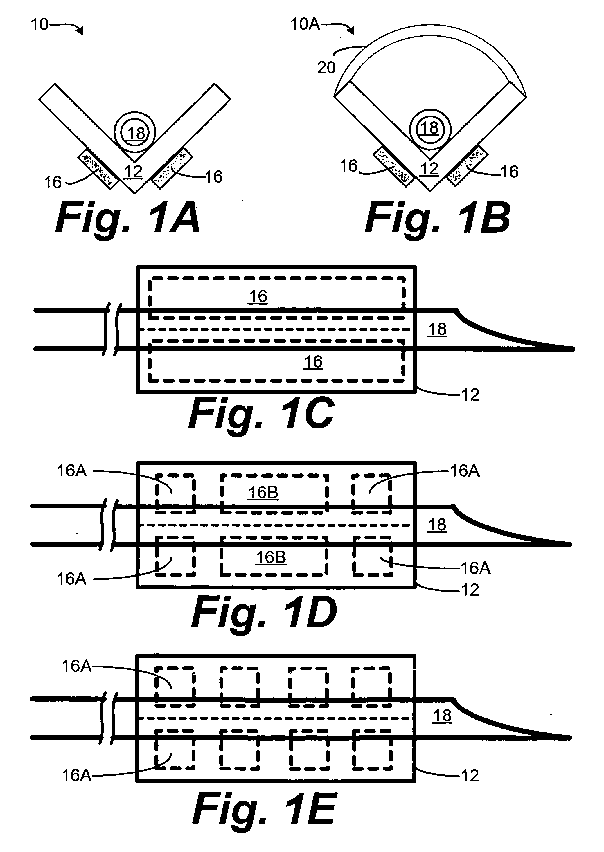
[0062]FIG. 1A is a schematic cross-section view of a needle / cannula guide device 10 according to an embodiment of the invention. The needle / cannula guide device 10 includes a V-block 12 that supports a needle or cannula 18. The V-block 12 includes two opposing sections that are coupled to each other at an apex. Magnetic strips 16 are positioned on an exterior portion of the V-block 12 that magnetically retain the cannula 18 within the V-block 12. A...


PUM


Abstract

A means for holding a selected cannula such that the cannula is controllably restricted in motion in all but one line, but still able to slide along the line relatively freely. The motion restricting force may be selectively varied, thereby allowing an unrestricted separation of the cannula and holding / guide device.

Description

PRIORITY CLAIM [0001] This application is claims priority to U.S. provisional patent application Ser. No. 60 / 621,349 filed Oct. 22, 2004. [0002] This application is a continuation-in-part of and claims priority to U.S. patent application filed Aug. 26, 2005 under U.S. Express Mail No. EV509173452US. [0003] This application claims priority to and is a continuation-in-part of U.S. patent application Ser. No. 11 / 119,355 filed Apr. 29, 2005, which claims priority to U.S. provisional patent application Ser. No. 60 / 566,127 filed Apr. 30, 2004. This application also claims priority to and is a continuation-in-part of U.S. patent application Ser. No. 10 / 701,955 filed Nov. 5, 2003, which in turn claims priority to and is a continuation-in-part of U.S. patent application Ser. No. 10 / 443,126 filed May 20, 2003. [0004] This application claims priority to and is a continuation-in-part of U.S. patent application Ser. No. 11 / 061,867 filed Feb. 17, 2005, which claims priority to U.S. provisional pa...

Claims


Application Information

Patent Timeline
Patent Type & Authority Applications(United States)
IPC IPC(8): A61B8/00A61B5/107A61B5/20A61B8/08G01S7/52G01S15/89G06T5/00G06T7/60
CPCA61B8/0833A61B8/0841A61B8/4455A61B17/3403A61B19/50A61B2017/00477A61B2017/00876A61B2017/3413A61B2019/5276A61B5/1075A61B5/204A61B8/0858A61B8/483G01S7/52036G01S7/52053G01S7/52085G01S15/8909G06T7/0012G06T2207/10132G06T2207/10136G06T2207/20061G06T2207/30004G06T2207/30044A61B34/10A61B2090/378G06T7/11G06T7/12G06T7/62
Inventor MCMORROW, GERALDSHANKLE, STEVEN J.GARRISON, RUSSELL A.
Owner VERATHON
Learn More