
Dual panel display

a dual-display, display technology, applied in the direction of instruments, polarising elements, optics, etc., can solve the problems of increasing the weight and thickness of the end product, not allowing light, thin and small products, and non-uniform light distribution on the main panel

Inactive Publication Date: 2007-05-03
INNOLUX CORP +1
View PDF5 Cites 17 Cited by
  • Summary
  • Abstract
  • Description
  • Claims
  • Application Information

AI Technical Summary

Benefits of technology

[0008] The present invention relates to a dual panel display that adjusts light-exiting capacity on both sides of the backlight module and prevents the problem mentioned above.
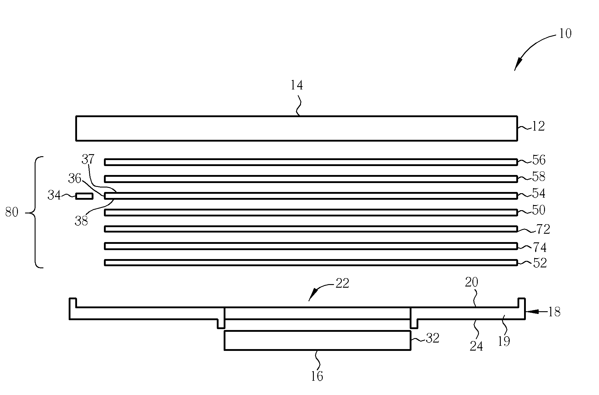
[0010] Since the dual display structure of the present invention uses the plurality of reflective polarizers positioned between the light guide plate of the backlight module and the first display panel or the second display panel, light can be controlled by rotating the included angle of the transmission axis of the reflective polarizers to provide uniform light on the first display panel and overcome the non-uniform brightness distribution phenomenon.

Problems solved by technology

This method increases the weight and thickness of the end product, and therefore does not allow for light, thin, and small products.
Since a light guide plate is shared between the main panel and the sub panel, there is another problem.
Therefore there is a non-uniform distribution of light on the main panel, i.e., light at the light-exiting opening of the main housing is dim and forms a shadow on the light-exiting opening.
This causes a difference of light intensity and color on the main panel.
There is still a non-uniform brightness distribution on the main panel even after fine tuning.
Using diffusers can improve this phenomenon, but the result is not good enough.
Using composite films like brightness enhancement films or diffusers to overcome this phenomenon substantially increases the cost and thickness of the dual-display LCD.

Method used


Image

  • Dual panel display
  • Dual panel display
  • Dual panel display

Examples


Embodiment Construction

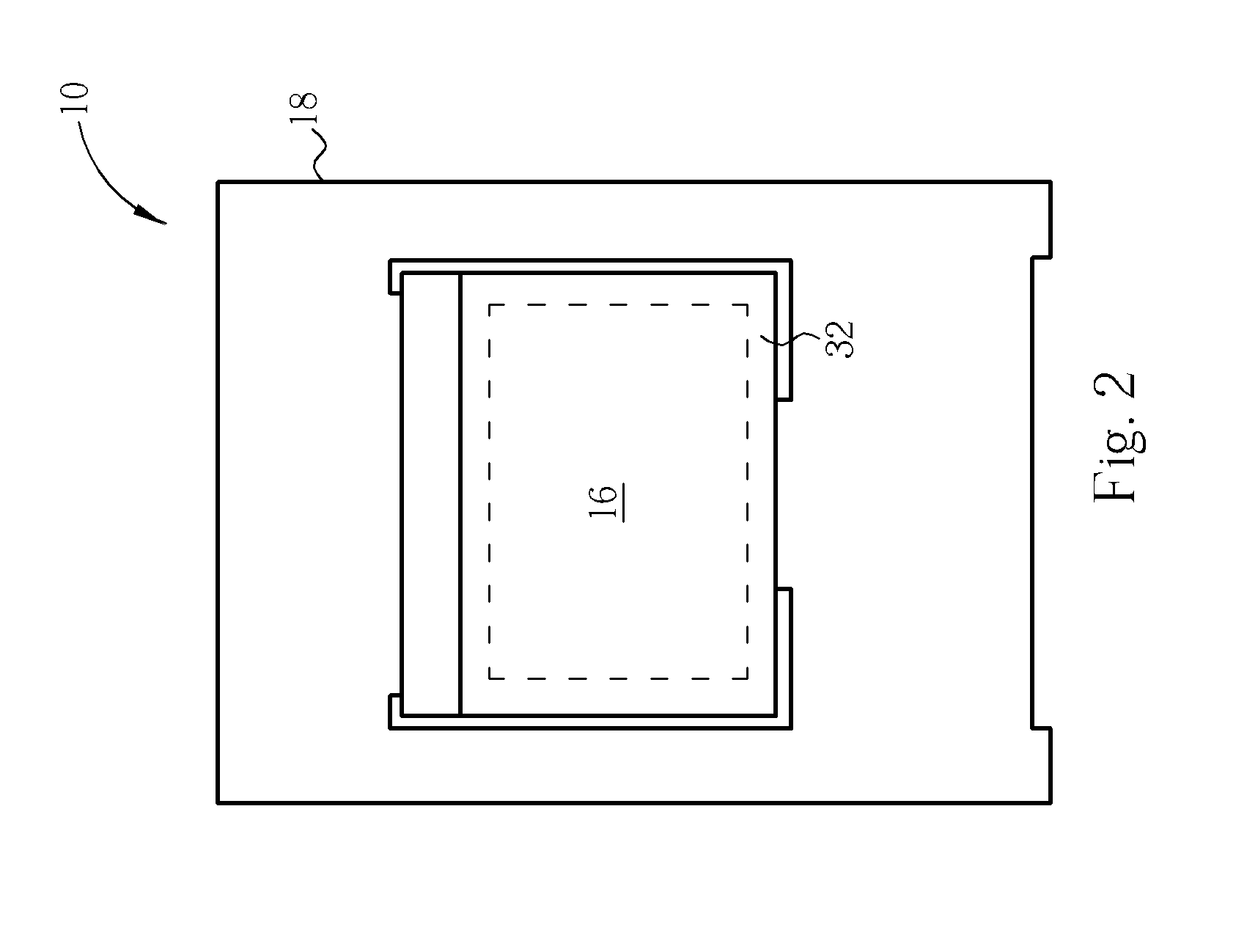
[0016] Please refer to FIGS. 1 and 2. FIG. 1 is a front-view diagram of a dual panel display 10 according to the present invention, and FIG. 2 is a rear-view diagram of a dual panel display 10. FIG. 3 is an exploded diagram of a dual panel display 10. As shown in FIG. 1, the dual panel display 10 of the present invention comprises a first display panel 12 which is an LCD panel, and the first display panel 12 comprises a first surface 14 which is the display face of the first display panel 12. A dashed-line area in FIG. 1 is the display area of the first display panel 12. The dual display structure 10 of the present invention also comprises a housing 18 which is used to hold and steady the backlight module 80 shown in FIG. 3 and the first display panel 12. FIG. 2 shows a reverse side of the dual display structure 10 in FIG. 1. As shown in FIG. 2, the dual display structure 10 of the present invention further comprises a second display panel 32 which is an LCD panel, and the second di...


PUM


Abstract

A dual panel display has a backlight module, a first display panel, a second display panel, and a plurality of reflective polarizers deposited between the first light-exit surface and the first display panel or the second light exit surface and the second display panel of the light guide plate in the backlight module.

Description

BACKGROUND OF THE INVENTION [0001] 1. Field of the Invention [0002] The present invention relates to a structure of a dual-display LCD, and more particularly, to a structure of a dual-display LCD to prevent a non-uniform brightness distribution on the main display panel. [0003] 2. Description of the Prior Art [0004] An LCD is a thin and electricity-saving flat display, which uses liquid crystal rotation angle and a polarized light layer to control light transmittance. Brightness is controlled by the transmittance. When color is constant, a liquid crystal remains in a steady state, and this is why the LCD has stable appearance without flicker. Because of the above-mentioned advantages, LCDs are applied in mobile phones, PDAs, notebook computers, and digital cameras. Recently, dual-display LCDs have been applied to various products. [0005] For example, many shell-type mobile phones use dual-display LCDs. The dual-display LCD has a main display panel and a sub-display panel. The sub-di...

Claims


Application Information

Patent Timeline
IPC IPC(8): G02B5/30
CPCG02B5/3025G02B6/0055G02B6/0056G02B6/0063G02F1/133536G02F2001/133342G02F1/133342
Inventor LI, RUI-YONGYU, CHUAN-PEI
Owner INNOLUX CORP
Learn More