
Shelf shipping clip

Inactive Publication Date: 2007-04-26
ILLINOIS TOOL WORKS INC
View PDF4 Cites 7 Cited by
  • Summary
  • Abstract
  • Description
  • Claims
  • Application Information

AI Technical Summary

Benefits of technology

[0015] A shim may extend from the beam and be configured to be positioned between the at least one shelf and at least one of the walls of the cabinet. The shim is configured to prevent lateral shifting of the at least one shelf within the cabinet.

Problems solved by technology

However, separately shipping the shelves and cabinet increases the costs of shipping, because two separate packing assemblies are shipped.
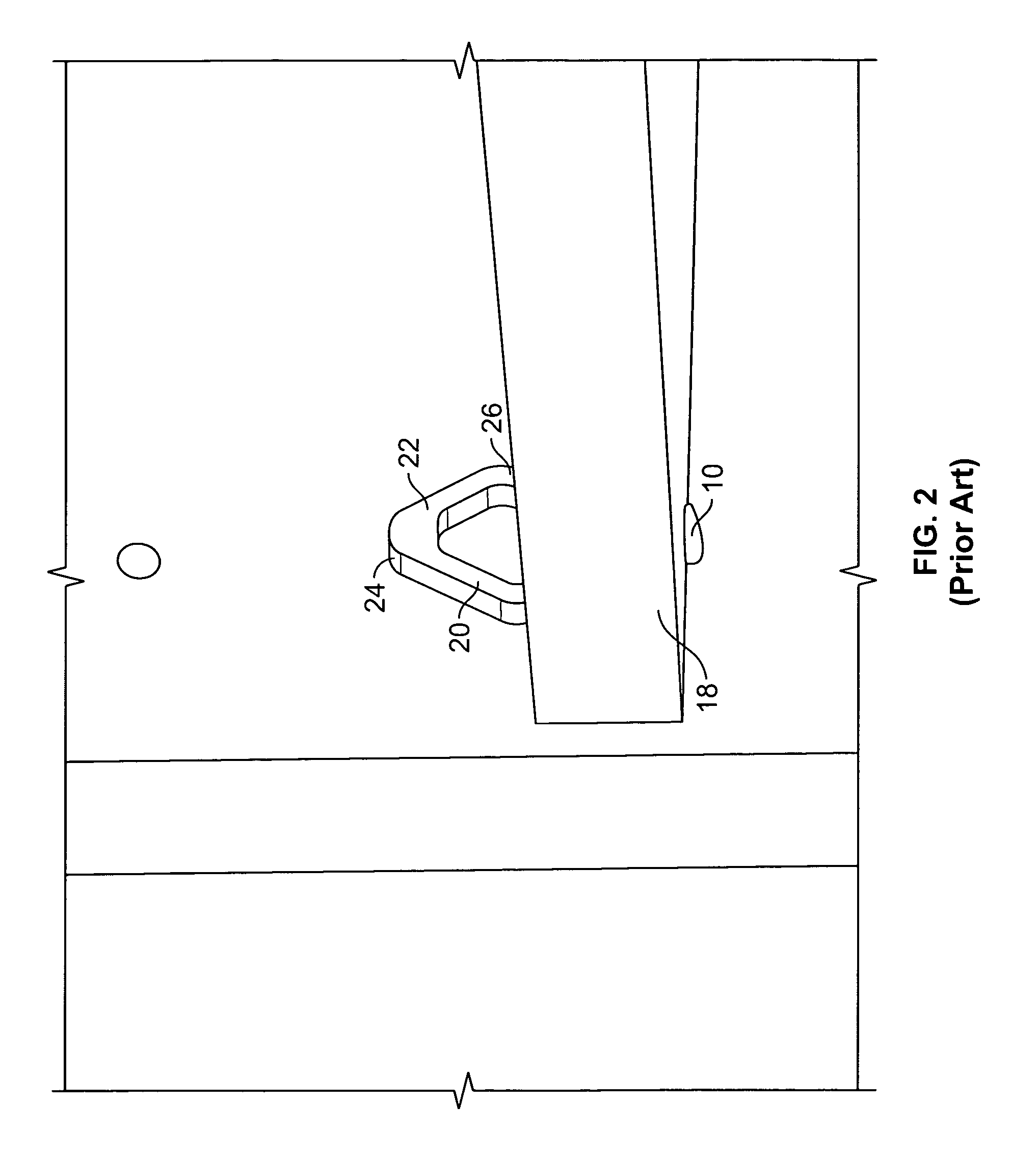
As such, the shelves 18 and cabinet walls may be susceptible to scratching or other such damage during shipping.

Method used


Image

  • Shelf shipping clip
  • Shelf shipping clip
  • Shelf shipping clip

Examples


Embodiment Construction

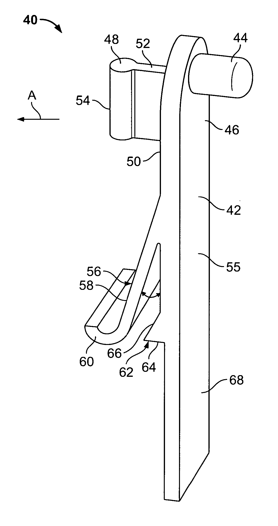
[0024]FIG. 5 illustrates an isometric view of a shipping clip 40 according to an embodiment of the present invention. The shipping clip 40 may be formed of various materials, such as rubber, or plastic. The shipping clip 40 includes a main beam 42 having a cabinet securing post 44 extending from a wall-abutting side 46. The cabinet securing post 44 is configured to be retained within a securing hole (not shown in FIG. 5) within a cabinet wall (not shown in FIG. 5).

[0025] A handle 48 extends from a shelf side 50 (which is opposite the wall-abutting side), and proximate the top of the main beam 42. That is, the handle 48 and the post 44 extend from opposite sides 50 and 46, respectively, of an upper portion of the main beam 42. The handle 48 may include a vertical fin 52 extending outwardly from the side 50. The vertical fin 52 may be integrally formed with a cylindrical post 54. The vertical fin 52 and the cylindrical post 54 may be ergonomically configured to allow easy grasping of...


PUM


Abstract

A shipping clip is configured to secure at least one shelf within a cabinet having walls and a base. The shipping clip includes a main beam having first and second side, and a biasing tab outwardly extending from the first side at an angle. The biasing tab is configured to exert a force into the shelf to compressively secure the shelf within the cabinet during shipping.

Description

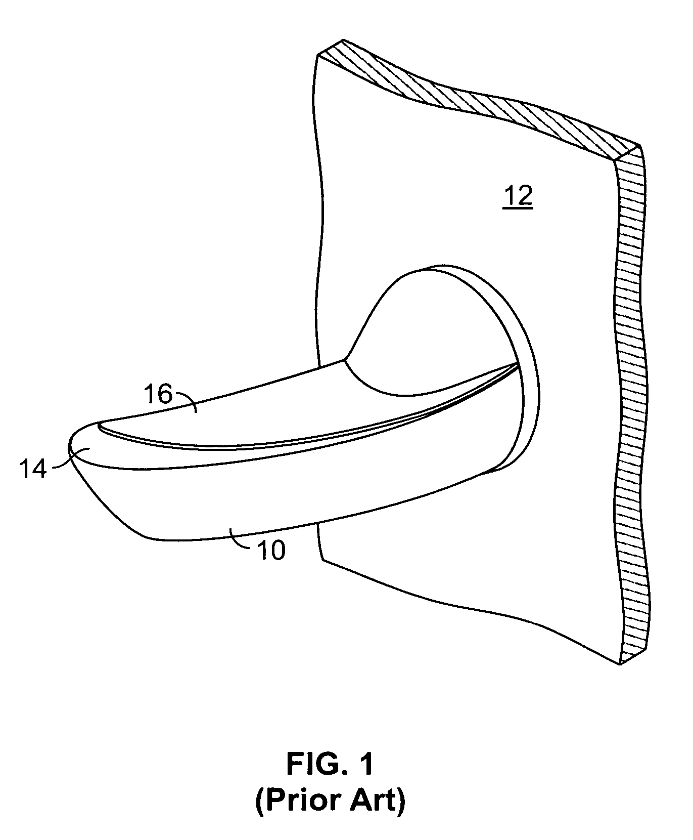
RELATED APPLICATIONS [0001] This application relates to and claims priority benefits from U.S. Provisional Patent Application No. 60 / 726,358 entitled “Shelf Shipping Clip,” filed Oct. 13, 2005, which is hereby incorporated by reference in its entirety.FIELD OF THE INVENTION [0002] Embodiments of the present invention generally relate to shipping clips, and more particularly to shipping clips for shelves. BACKGROUND OF THE INVENTION [0003] Various cabinets and bookcases include a plurality of shelves that may be secured within the cabinets and bookcases through a plurality of pins. FIG. 1 illustrates an isometric view of a conventional shelf pin 10 secured within a cabinet wall 12. The shelf pin 10 includes a post or tab (not shown) removably secured within a reciprocal securing opening (not shown) within the cabinet wall 12. A shelf support beam 14 having a flat surface 16 extends outwardly from the cabinet wall 12. Typically, two shelf pins 10 are spaced apart from one another on a...

Claims


Application Information

Patent Timeline
IPC IPC(8): A47G29/02
CPCA47B96/068
Inventor DOWNING, MARK
Owner ILLINOIS TOOL WORKS INC
Learn More