
Slidable pivoting roof rack

a roof rack and sliding technology, applied in the field of vehicle carrying systems, can solve the problems of soiled clothing plus scratches and other damage to the vehicle, the roof rack does not include features for securely holding particular types of equipment, and the current availability of roof racks

Inactive Publication Date: 2007-04-26
MCKENZIE ROBERT
View PDF9 Cites 36 Cited by
  • Summary
  • Abstract
  • Description
  • Claims
  • Application Information

AI Technical Summary

Benefits of technology

[0011] The present invention is directed to an apparatus that meets the above-mentioned needs and may provide additional advantages and improvements that will be recognized by those skilled in the art upon review of the present disclosure. The apparatus according to the present invention encompasses a roof rack that may be installed on the roof of a vehicle to securely transport a variety of cargo and that provides features that allow heavy or unwieldy cargo to be conveniently placed onto the roof rack or removed from the roof rack without damage to the vehicle or injury to the user.
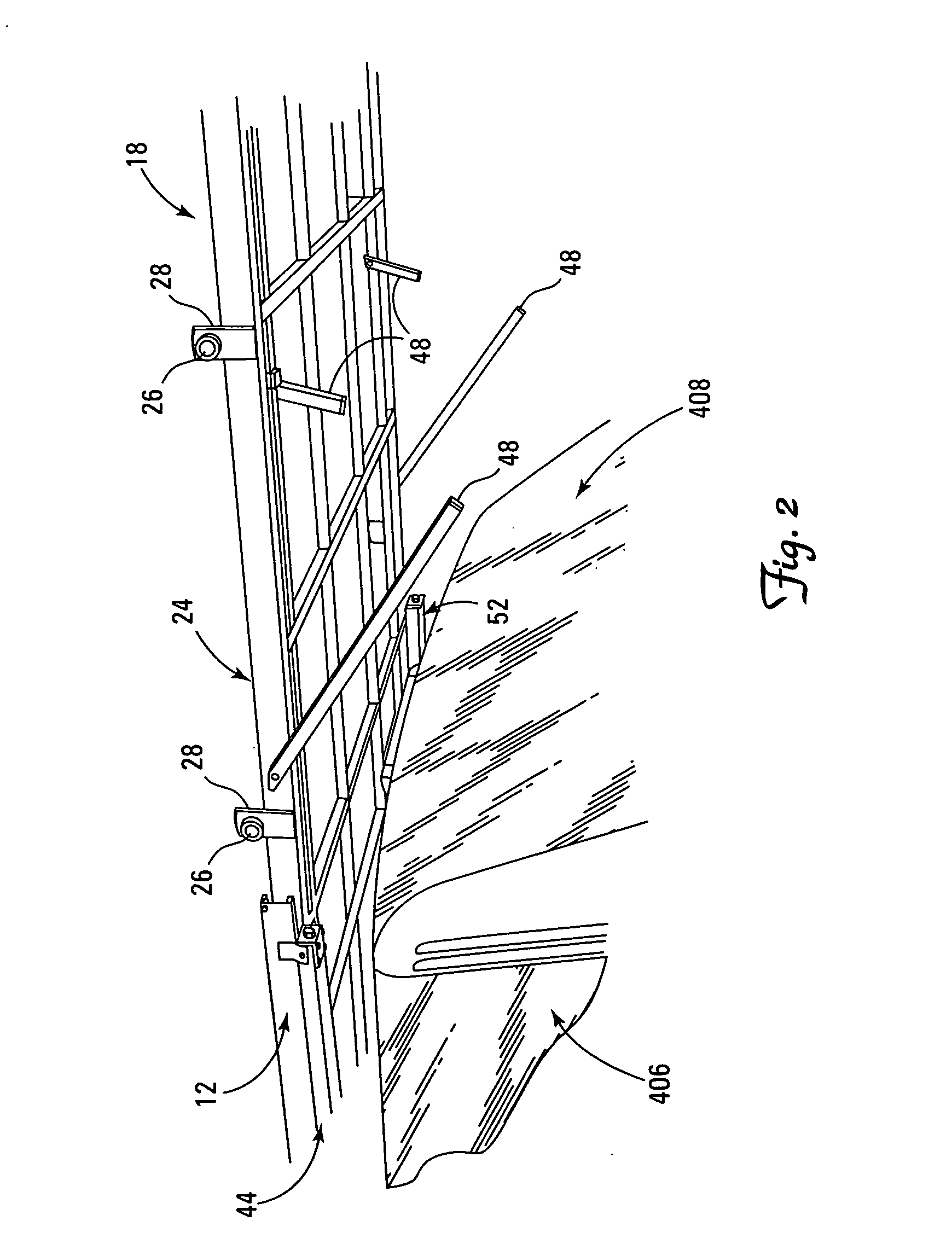
[0012] A roof rack according to the present invention has two components, a base and a tray. The base is attached to the roof of a vehicle. The tray is attached by pivots to moveable sliders receivably contained in channel components of the base, so that the position of the tray relative to the base changes as the position of the sliders within the channels is changed and the tray may rotate relative to the base about the pivots on the moveable sliders.
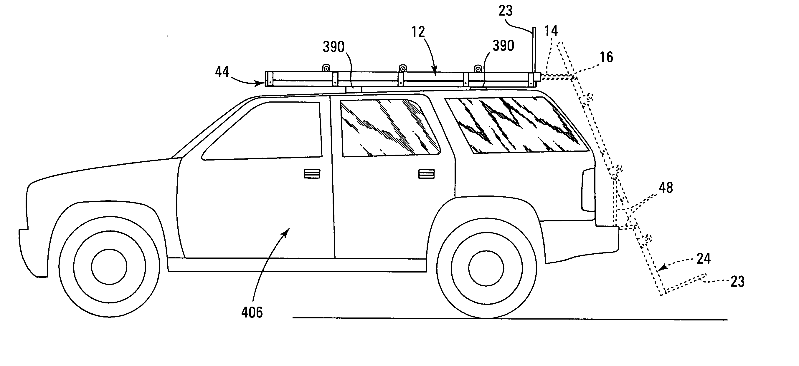
[0015] When the tray is in the loading position, the tray is extended from the base and rotated so as to make an oblique angle with the base such that the tray extends below the plane defined by the roof of the vehicle. Cargo may be placed on the tray or removed from the tray when the tray is in the loading position. When the tray is in the loading position, user access to the tray is improved which facilitates the placement of cargo on the tray and the removal of cargo from the tray.
[0017] The base attaches to the roof of the vehicle. In some embodiments, the base may have a number of legs to support the base at a fixed location above the surface of the vehicle roof. The legs may have rubber protectors on the ends that serve to prevent damage to the vehicle. In other embodiments, the base may be designed to be permanently attached to the roof of a vehicle in a number of ways such as by welding the base to the vehicle or bolting the base to the vehicle.

Problems solved by technology

These generalized load carriers do not include features for securely holding particular types of equipment.
User accessibility is a problem with roof racks provided by the manufacturer as well as aftermarket roof racks, particularly the ability of a user to place large ungainly cargo such as a canoe or a bicycle on a roof rack, position the cargo properly on the roof rack, and then fasten that cargo to the roof rack.
Similar problems exist with vans and pickup trucks having caps or removable hardtops installed over their cargo decks.
Other problems are also inherent in currently available roof racks.
In order to load a roof rack, most users must stretch and lean against the vehicle which can result in soiled clothing plus scratches and other damage to the vehicle from buttons and zippers on clothing.
Furthermore, the equipment items placed in the roof rack may likewise include metal or abrasive surfaces that may scratch or mar the paint and otherwise cause damage to the vehicle if not handled with appropriate control while being placed in the roof rack and secured.
These problems may be further aggravated by loading and unloading the roof rack a number of times.
Loading heavy or unwieldy cargo into existing roof racks also places the user at some risk of injury.
A user may resort to balancing on bumpers, hoods, trunks, and in vehicle doorways while loading or unloading cargo, with the obvious potential for injury.
The act of lifting heavy or unwieldy objects onto a vehicle roof also has the potential to cause various injuries.

Method used


Image

  • Slidable pivoting roof rack
  • Slidable pivoting roof rack
  • Slidable pivoting roof rack

Examples


Embodiment Construction

[0032] The present invention relates to a roof rack that may be installed upon the roof of a vehicle to facilitate placement of cargo thereon. Various embodiments of apparatus and methods in accordance with the present invention are illustrated throughout the figures for exemplary purposes and ease of description.

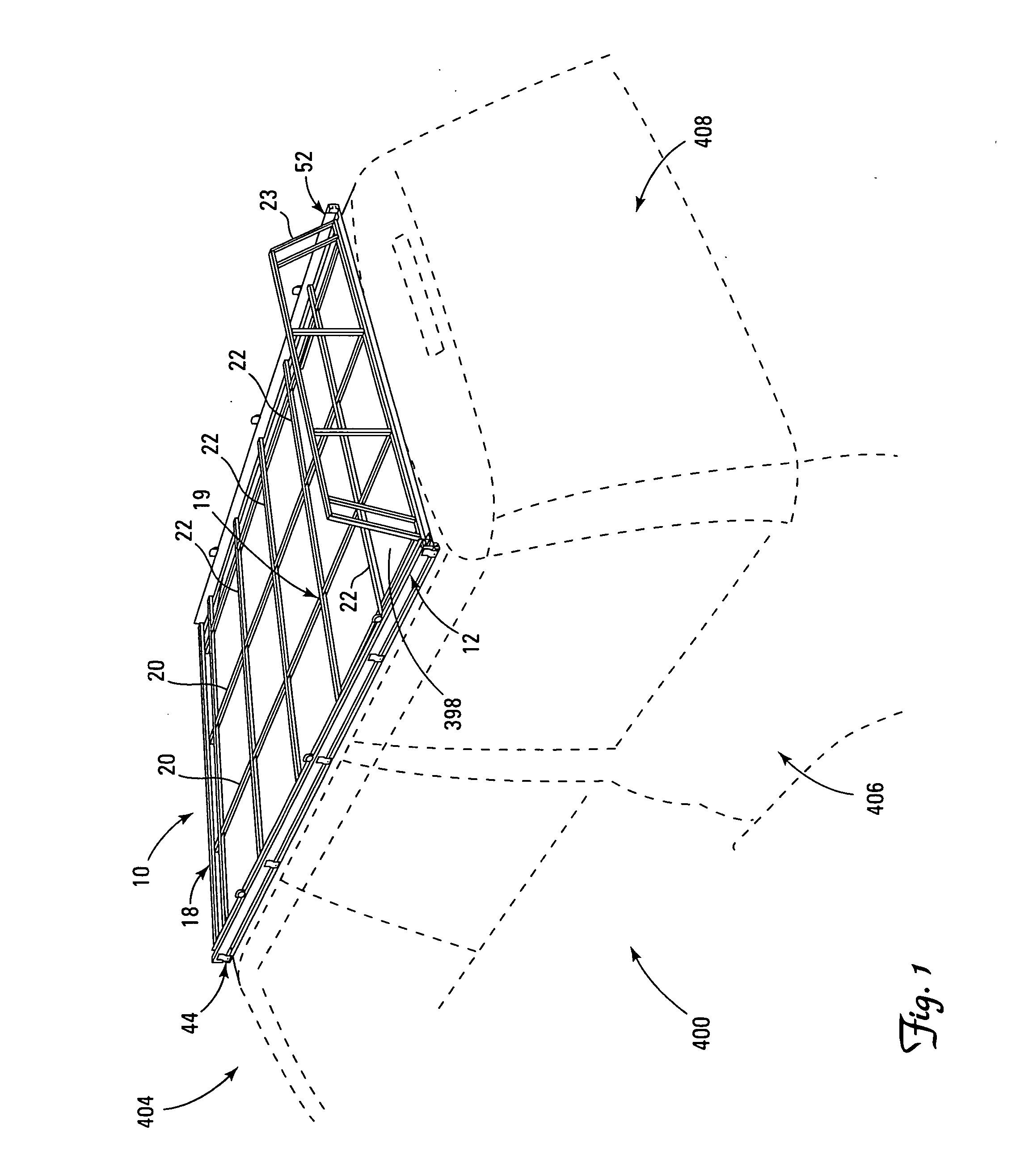
[0033]FIG. 1 shows a perspective view of an embodiment of the present invention 10 placed upon the roof 398 of a vehicle 400. The perspective view shows both the vehicle side 406 and the vehicle rear 408 in phantom. The vehicle front 404 is also indicated in this figure. The roof rack of the present invention 10 consists of two main components, a base 44 that engages the roof 398 of the vehicle 400 and a tray 18.

[0034] The tray 18 is slidably and pivotably mounted to the base, so that the tray 18 may be placed in a plurality of positions with respect to the base 44 and rotated with respect to the base 44. The tray 18 has two operational positions with respect to the base ...


PUM


Abstract

A roof mounted carrying system can be installed on the roof of a vehicle to securely transport a variety of cargo. The carrying system provides features that allow heavy and unwieldy cargo to be conveniently placed or removed from the carrying system without damage to the vehicle or injury to the user. The carrying system includes a base and a tray. The base is attached to the roof of a vehicle. The tray can be slid outwards from the base and rotated in downward direction so that cargo can be conveniently loaded onto the tray. After cargo is placed on the tray, the tray is then rotated upwards and slid back into the base, so that the tray is integral with the base.

Description

BACKGROUND OF THE INVENTION [0001] 1. Field of the Invention [0002] The present invention relates to vehicular carrying systems and, more particularly to roof mounted carrying systems. [0003] 2. Description of the Related Art [0004] Many vehicles are equipped by the manufacturer with roof racks. A standard roof rack comprises a pair of spaced parallel rails or load bars, fixedly attached to the roof and aligned parallel to the centerline of the roof or transversely to it. The rails are elevated a slight distance from the roof surface, generally three to five inches. The ends of the rails have end brackets which attach to the roof and hold the rails at the predetermined height. In a common configuration, the brackets for the two transverse rails are adjustably mounted in fixed linear tracks along each side edge of the roof, providing the user with the capability of setting the spacing between the two transverse rails. [0005] These generalized load carriers do not include features for...

Claims


Application Information

Patent Timeline
IPC IPC(8): B60R9/042B60P9/00B60R9/00
CPCB60R3/005B60R9/0485B60R9/0423
Inventor MCKENZIE, ROBERT
Owner MCKENZIE ROBERT
Learn More