
Slat tilting device for a window covering

a technology of window covering and tilting device, which is applied in the direction of door/window protective device, building components, construction, etc., can solve the problems of reducing transmission efficiency and high cost, and achieve the effect of avoiding hindran

Inactive Publication Date: 2007-04-26
HUANG TAI LONG
View PDF8 Cites 3 Cited by
  • Summary
  • Abstract
  • Description
  • Claims
  • Application Information

AI Technical Summary

Benefits of technology

[0006] The object of the present invention is to provide a slat tilting device for a window covering which is easy and convenient to operate which has an enhanced force transmission efficiency, and which has a less number of component parts.
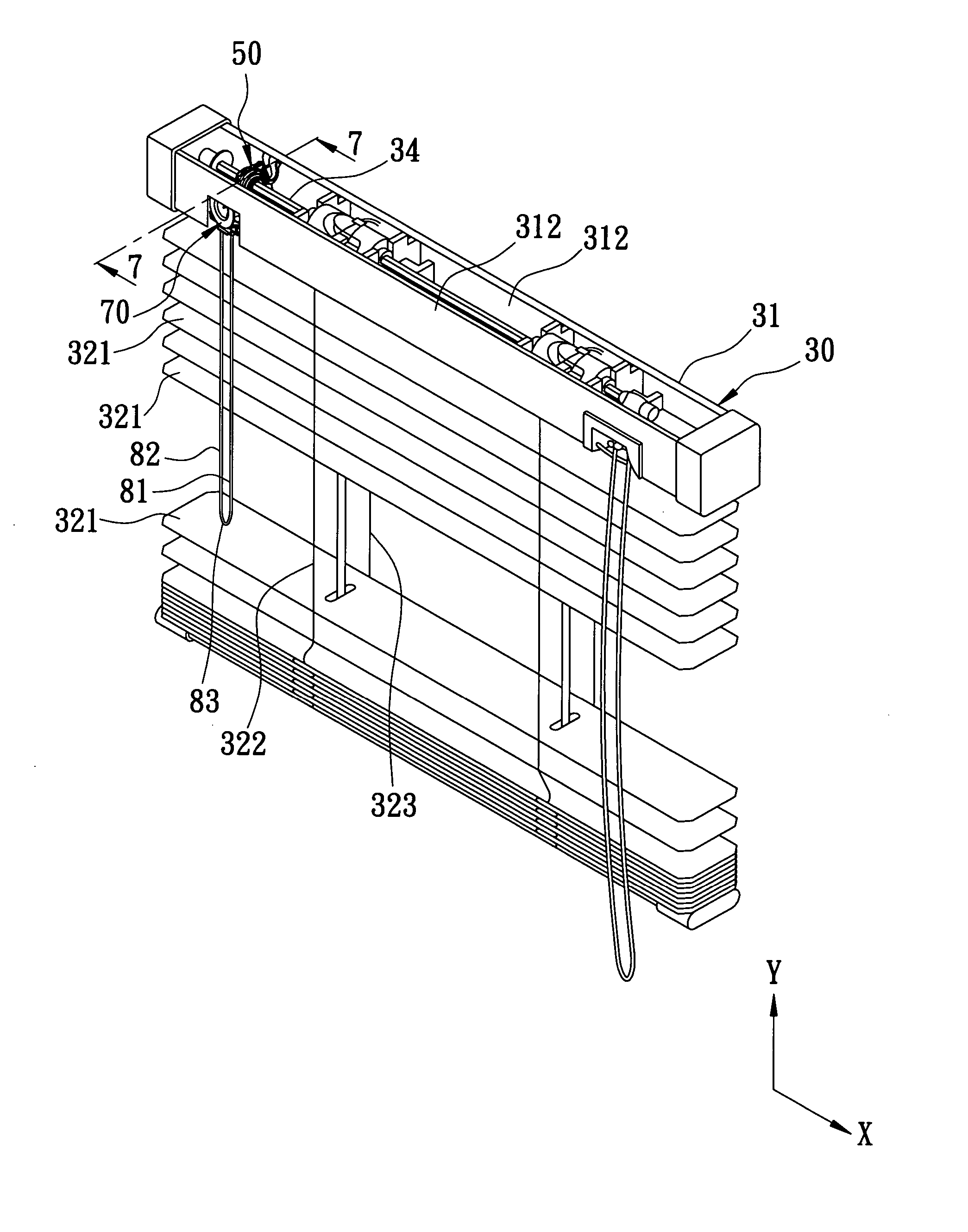
[0008] The device includes a mounting seat having a base wall and a bearing wall. The base wall is adapted to be fixedly mounted on the header rail, and has a horizontal surface which extends in the longitudinal direction and which has front and rear end regions opposite to each other in a transverse direction perpendicular to the upright and longitudinal directions, and a middle region disposed between the front and rear end regions. The front end region has left and right holes extending through the base wall in the upright direction. The bearing wall extends from the middle region in the upright direction to terminate at a bearing surface. An operating unit includes a journal segment, a driving shaft, and a pulley roller. The journal segment is journalled on the bearing surface to be rotatable about a first rotating axis, and has rear and front ends connected to the driving shaft and the pulley roller. The driving shaft extends along the first rotating axis that extends rearwardly and downwardly toward the horizontal surface. A driven wheel is driven by the driving shaft to rotate about a second rotating axis, and is adapted to be connected to the tilt shaft so as to align the second rotating axis with the turning axis for turning the tilt shaft, thereby pulling the front or rear cord segment for tilting the slats. An operating cord is wound on the pulley roller, and is adapted to be disposed forwardly of the slats. The operating cord has left and right pulled segments which extend downwardly and respectively through the left and right holes to terminate at a joined gripped end for manual operation such that pulling of either the left or right pulled segment results in rotation of the pulley roller about the first rotating axis so as to enable the driving shaft to turn the tilt shaft, and such that when the left and right pulled segments stand still, the joined gripped end is disposed forwardly and away from the slats so as to avoid hindrance caused by the slats during the pulling operation of the operating cord.

Problems solved by technology

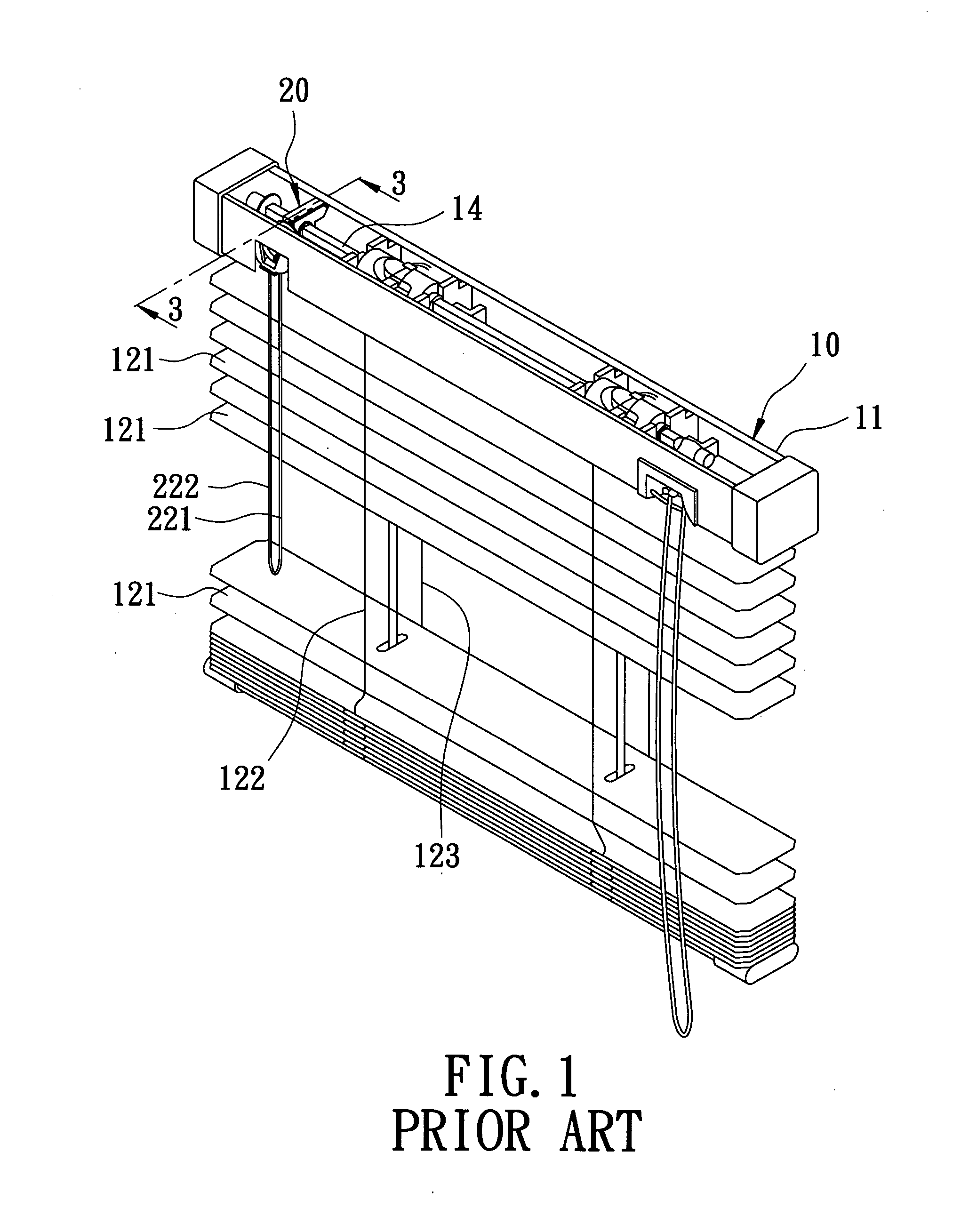
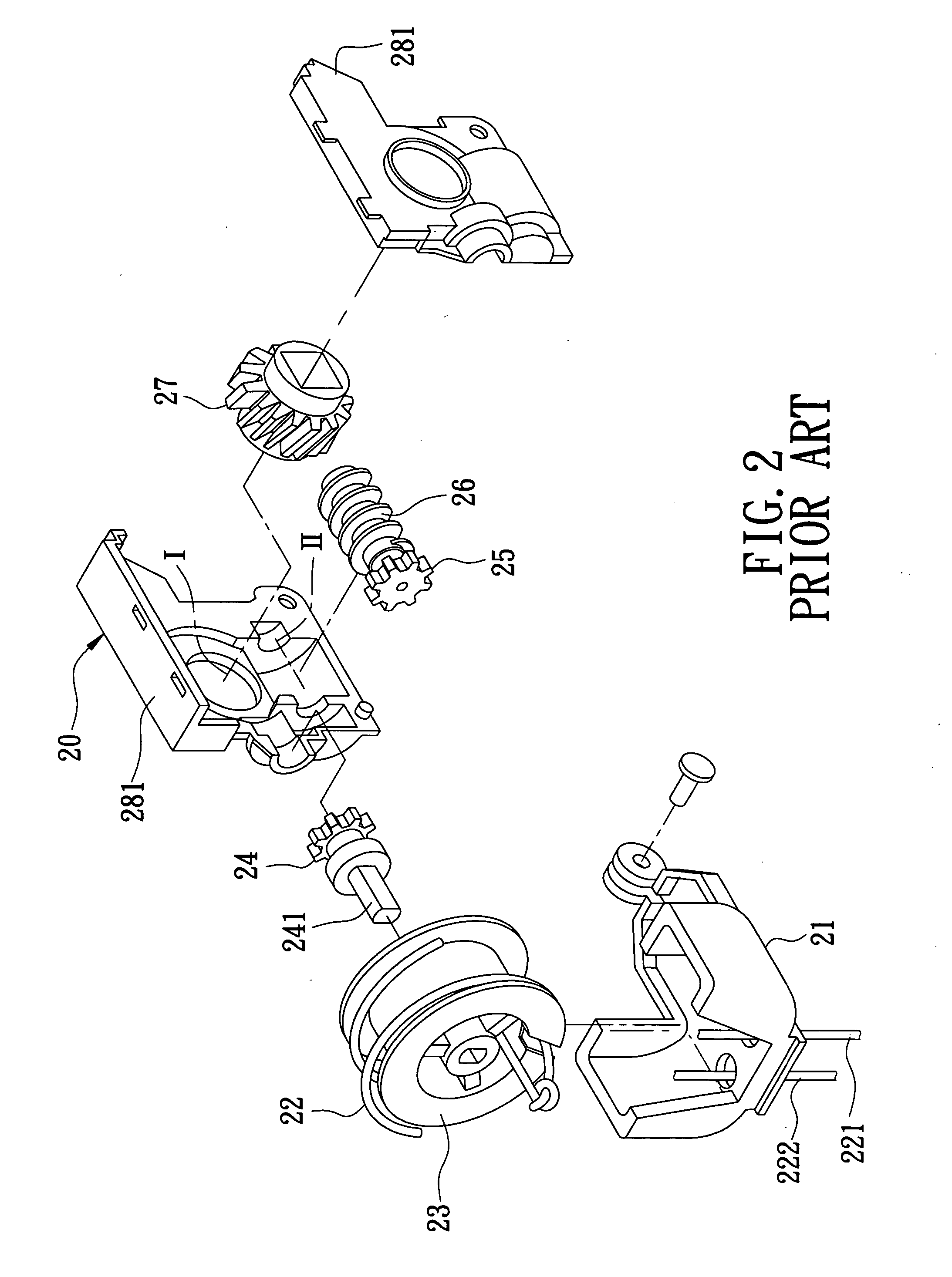
In addition, the drive gear 24 is coupled with the roller 23 through the non-circular drive axle 241, which tends to wear at the engagement between the roller 23 and the drive axle 241, thereby resulting in malfunctioning.
Besides, many component parts are needed to transmit the rotational force of the roller 23 to the tilt shaft 14, thereby resulting in high costs and reduced transmission efficiency.

Method used


Image

  • Slat tilting device for a window covering
  • Slat tilting device for a window covering
  • Slat tilting device for a window covering

Examples


Embodiment Construction

[0017] Referring to FIG. 4, the preferred embodiment of a slat tilting device according to the present invention is shown to be mounted on a header rail 31 of a Venetian blind 30. The Venetian blind 30 includes the header rail 31, which extends in a longitudinal direction (X), a plurality of slats 321 disposed beneath the header rail 31 and connected to one another in an upright direction (Y) perpendicular to the longitudinal direction (X) by a connecting cord that includes front and rear cord segments 322,323 that are respectively disposed forwardly and rearwardly of the slats 321, and a tilt shaft 34 which is mounted on the header rail 31 and which is turnable relative thereto about a turning axis in the longitudinal direction (X) so as to pull either the front or rear cord segment 322,323 to thereby tilt the slats 321.

[0018] With reference to FIGS. 4 to 7, the slat tilting device is shown to comprise a mounting seat 40, a shell 50, an operating unit 70, a driven wheel 60, and an...


PUM


Abstract

A slat tilting device for tilting slats of a window covering includes a mounting seat having a horizontal surface and a bearing wall for rotatably supporting a journal segment about a first rotating axis that extends rearwardly and downwardly toward the horizontal surface. The journal segment is connected to a driving shaft and a pulley roller. A driven wheel is rotated by the driving shaft so as to drive a tilt shaft to turn, thereby tilting the slats. An operating cord is wound on the pulley roller, and has two pulled segments that extend downwardly and that are pulled to result in rotation of the pulley roller so as to enable the driving shaft to turn the tilt shaft. A joined gripped end of the operating cord is disposed forwardly and away from the slats to avoid hindrance caused by the slats during the pulling operation.

Description

BACKGROUND OF THE INVENTION [0001] 1. Field of the Invention [0002] This invention relates to a slat tilting device for a window covering, more particularly to a slat tilting device which can be easily operated to tilt slats of the window covering. [0003] 2. Description of the Related Art [0004] Referring to FIGS. 1 to 3, in U.S. Pat. No. RE 37143 E, entitled “Slat Angle Adjusting Device For a Venetian Blind,” there is disclosed a Venetian blind 10 which includes a header rail 11, a plurality of slats 121 disposed beneath the header rail 11 and connected to one another by a connecting cord that includes front and rear cord segments 122,123, a tilt shaft 14 turnable relative to the header rail 11 to pull either the front or rear cord segment 122,123 to thereby tilt the slats, and a tilt angle adjusting device 20. The tilt angle adjusting device 20 includes a support bracket 21 which is mounted within the header rail 11, a roller 23 which is rotatably received in the support bracket 2...

Claims


Application Information

Patent Timeline
IPC IPC(8): E06B9/307
CPCE06B9/307E06B2009/285
Inventor HUANG, TAI-LONG
Owner HUANG TAI LONG
Learn More