
Die for extrusion-molding and method for manufacturing porous ceramic member

Active Publication Date: 2007-04-19
IBIDEN CO LTD
View PDF94 Cites 99 Cited by
  • Summary
  • Abstract
  • Description
  • Claims
  • Application Information

AI Technical Summary

Benefits of technology

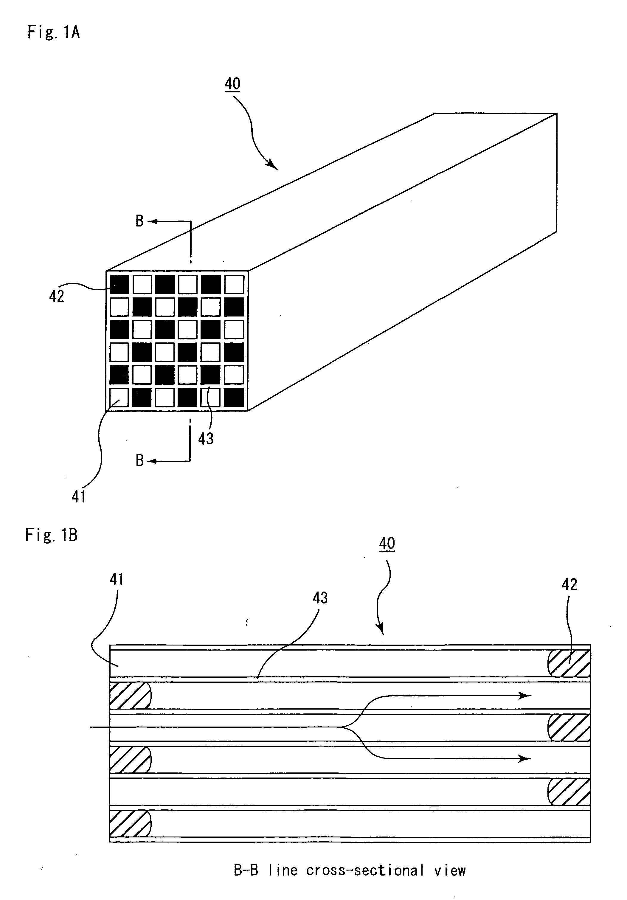
[0028] A method for manufacturing a porous ceramic member in accordance with the present invention is a method for manufacturing a porous ceramic member for manufacturing a porous ceramic member in which a plurality of cells are placed in parallel with one another in the longitudinal direction with a partition wall therebetween, by using a die for extrusion-molding comprising:
[0028] A method for manufacturing a porous ceramic member in accordance with the present invention is a method for manufacturing a porous ceramic member for manufacturing a porous ceramic member in which a plurality of cells are placed in parallel with one another in the longitudinal direction with a partition wall therebetween, by using a die for extrusion-molding comprising:

Problems solved by technology

Recently, particulate matters (hereinafter, referred to as PM) contained in exhaust gases that are discharged from internal combustion engines for vehicles such as a bus, a truck and the like, construction equipment and the like, have raised serious problems as contaminants harmful to the environment and the human body.

Method used


Image

  • Die for extrusion-molding and method for manufacturing porous ceramic member
  • Die for extrusion-molding and method for manufacturing porous ceramic member
  • Die for extrusion-molding and method for manufacturing porous ceramic member

Examples


examples

[0120] The following description will discuss the present invention in detail by means of examples; however, the present invention is not intended to be limited by these examples.

examples 1 to 9

, Comparative Examples 1 to 6

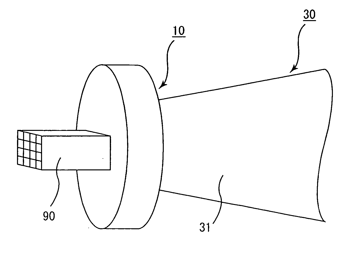
[0121] First, using a hard metal, the die for extrusion-molding 10 as shown in FIGS. 6A and 6B, which comprises the material supplying part, the molding groove part and the outer frame for fixing the die main body comprising the molding groove part and the material supplying part to the front end of the extrusion-molding apparatus, where the thickness X of the molding groove part, the thickness Y of the material supplying part, and the thickness Z of the die holding part of the outer frame were set to the values shown in Table 1-1, was manufactured.

[0122] Next, the die for extrusion molding 10 was fixed to the extrusion-molding apparatus 30 shown in FIG. 6B, and a mixed composition mainly composed of silicon carbide was charged into the extrusion-molding apparatus 30. By carrying out the extrusion-molding process continuously at the pressure shown in Table 1-1, the molded body 90 was continuously manufactured at the molding speed of 4000 mm / min, and the...


PUM

PropertyMeasurementUnit
Areaaaaaaaaaaa
Areaaaaaaaaaaa
Distanceaaaaaaaaaa

Abstract

A die for extrusion-molding in accordance with the present invention comprises: a molding groove part, a material supplying part, and an outer frame for fixing a die main body comprising the molding groove part and the material supplying part to the front end of an extrusion-molding apparatus, wherein the die main body has a form in which the plate-shaped molding groove part smaller than the material supplying part is provided at almost the middle of the plate-shaped material supplying part such that it protrudes from the material supplying part, the outer frame comprises: a die holding part which is provided such that it covers the material supplying part around the molding groove part; and a peripheral part which is provided near the die holding part, and supposing that the thickness of the molding groove part is X, the thickness of the material supplying part is Y, and the thickness of the die holding part of the outer frame is Z, these X, Y and Z are allowed to satisfy the inequalities (1) about 3≦X≦about 6, (2) about 5≦Y≦about 10, (3) about 3.5≦Z≦about 8.5, (4) about 0.8<Y / X<about 2.5, and (5) about 1<Z / X<about 2.

Description

CROSS REFERENCE TO RELATED APPLICATIONS [0001] This application claims priority of PCT / JP2006 / 316178 filed on Aug. 17, 2006, which claims priority of Japanese Patent Application No. 2005-292367 filed on Oct. 5, 2005. The contents of these applications are incorporated herein by reference in their entirety. BACKGROUND OF THE INVENTION [0002] 1. Field of the Invention [0003] The present invention relates to a die for extrusion-molding that is used upon manufacturing of a porous ceramic member, and a method for manufacturing a porous ceramic member using this die for extrusion-molding. [0004] 2. Discussion of the Background [0005] Recently, particulate matters (hereinafter, referred to as PM) contained in exhaust gases that are discharged from internal combustion engines for vehicles such as a bus, a truck and the like, construction equipment and the like, have raised serious problems as contaminants harmful to the environment and the human body. [0006] There have been proposed various...

Claims


Application Information

Patent Timeline
IPC IPC(8): B29C47/00B29C48/11B29C48/12B29C48/32
CPCB28B3/26B28B3/269B29C47/0028B29C47/12B29L2031/60B29C48/11B29C48/12
Inventor YAMADA, TAKEHISA
Owner IBIDEN CO LTD
Learn More