
Power generation in watercraft

a technology for watercraft and power generation, applied in the direction of vessel auxiliary drives, marine propulsion, vessel construction, etc., can solve the problems of not producing much power, polluting the environment, and being noisy,

Inactive Publication Date: 2007-04-19
GUDMUNDSON PETER
View PDF13 Cites 5 Cited by
  • Summary
  • Abstract
  • Description
  • Claims
  • Application Information

AI Technical Summary

Problems solved by technology

Some electrical power generation systems include solar panels containing arrays of solar cells (or photovoltaic cells) for converting solar energy into electricity, but such devices do not produce much power and are often not aesthetically pleasing.
Electrical power generation systems that include generators driven by diesel or gasoline motors are often used, but these systems pollute the environment, are typically noisy, etc.

Method used


Image

  • Power generation in watercraft
  • Power generation in watercraft
  • Power generation in watercraft

Examples


Embodiment Construction

[0011] In the following detailed description of the invention, reference is made to the accompanying drawings that form a part hereof, and in which are shown, by way of illustration, specific embodiments in which the invention may be practiced. In the drawings, like numerals describe substantially similar components throughout the several views. These embodiments are described in sufficient detail to enable those skilled in the art to practice the invention. Other embodiments may be utilized and structural, logical, and electrical changes may be made without departing from the scope of the present invention. The following detailed description is, therefore, not to be taken in a limiting sense, and the scope of the present invention is defined only by the appended claims and equivalents thereof.

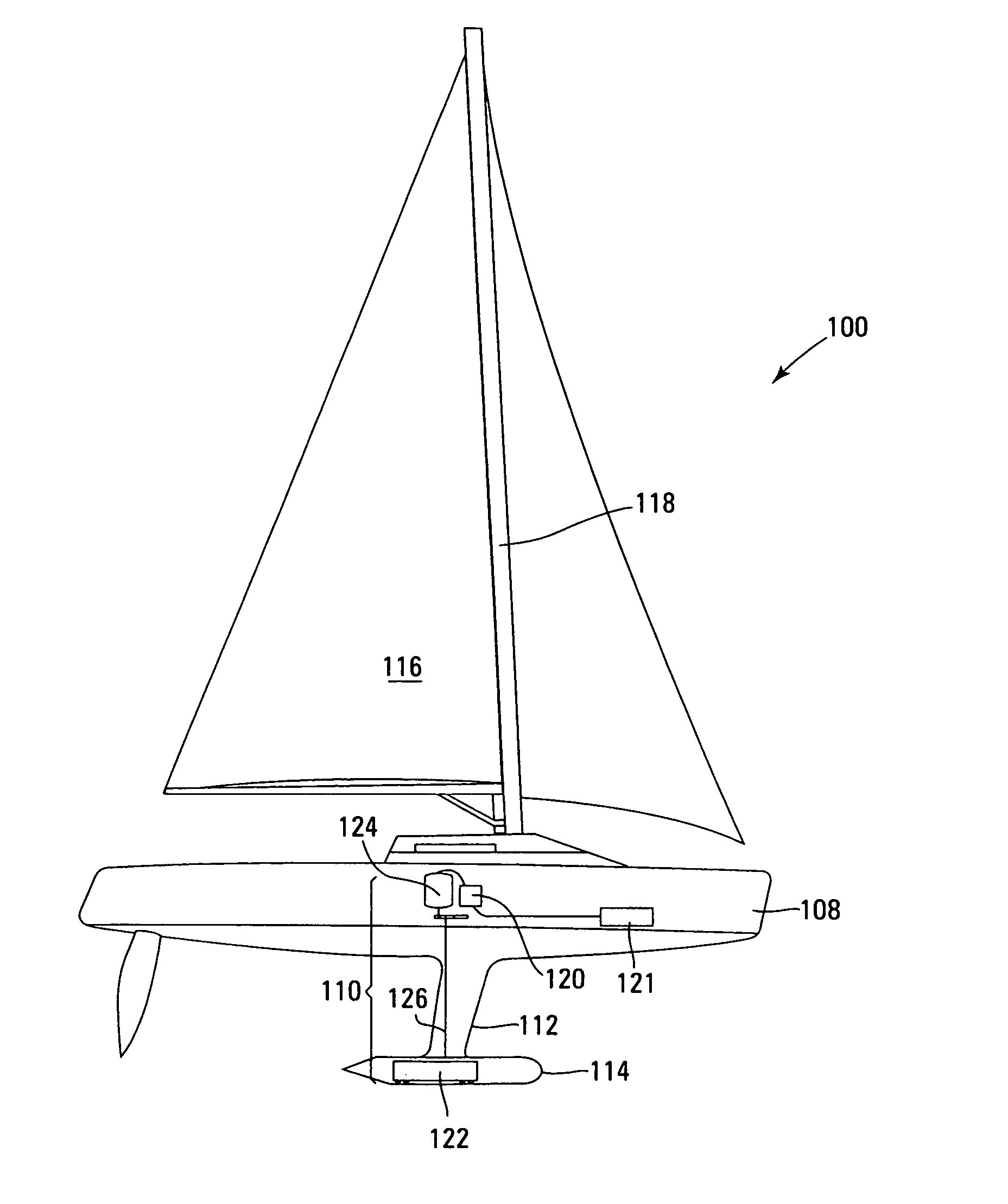
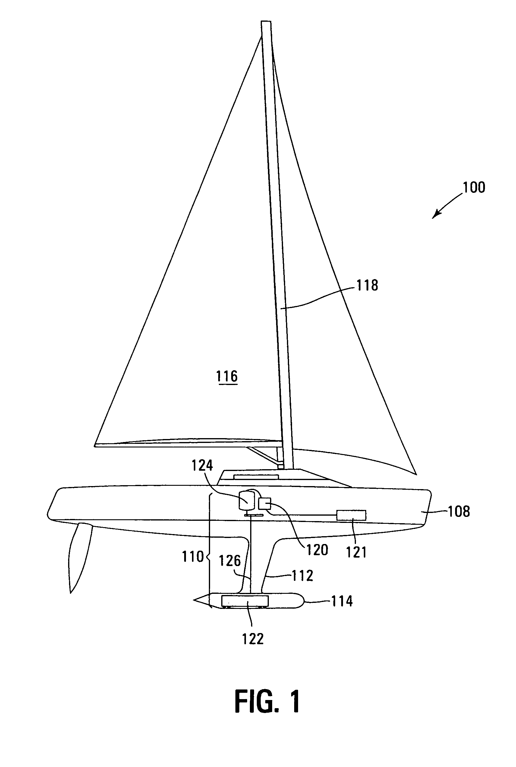
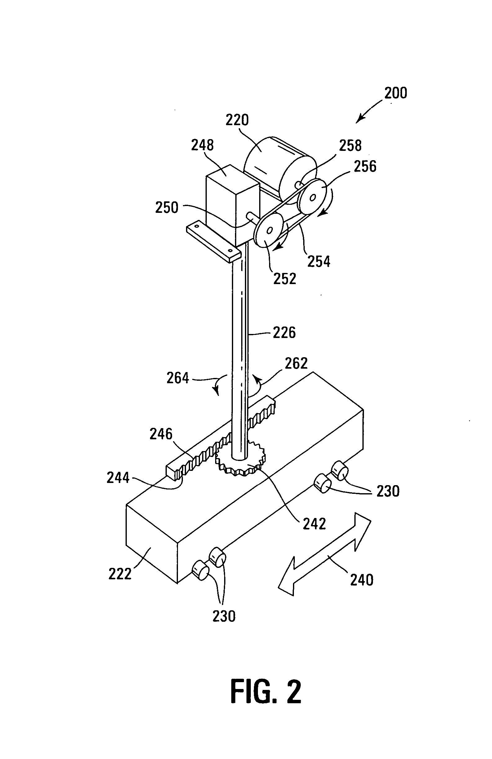
[0012]FIG. 1 illustrates a watercraft 100, such as a sailboat, according to one embodiment. Watercraft 100 includes a hull 108. A keel 112 protrudes from an exterior of hull 108. For one embo...


PUM


Abstract

An electrical power generation system for watercraft including movable ballast, an electrical generator, and a shaft connected between the ballast and the electrical generator.

Description

TECHNICAL FIELD OF THE INVENTION [0001] The present invention relates generally to power generation and in particular the present invention relates to power generation in watercraft. BACKGROUND OF THE INVENTION [0002] Watercraft, such as sailboats, often have one or more electrical devices, such as navigation equipment, autopilots, DVD players, lights, etc. Therefore, many sailboats are equipped with electrical power generation systems and electrical power storage devices. Some electrical power generation systems include solar panels containing arrays of solar cells (or photovoltaic cells) for converting solar energy into electricity, but such devices do not produce much power and are often not aesthetically pleasing. Electrical power generation systems that include generators driven by diesel or gasoline motors are often used, but these systems pollute the environment, are typically noisy, etc. [0003] For the reasons stated above, and for other reasons stated below which will becom...

Claims


Application Information

Patent Timeline
Patent Type & Authority Applications(United States)
IPC IPC(8): B60L11/02B63H21/17B60L11/16B60L50/10B60L50/30
CPCB63J3/04Y02T10/70B63B2035/009
Inventor GUDMUNDSON, PETER
Owner GUDMUNDSON PETER
Learn More