
Channel configuration and bandwidth allocation in multi-hop cellular communication networks

a multi-hop cellular communication and channel configuration technology, applied in the field of telecommunications, can solve the problems of limited coverage and known limitations of single-hop cellular networks

Active Publication Date: 2007-04-12
SAMSUNG ELECTRONICS CO LTD
View PDF12 Cites 127 Cited by
  • Summary
  • Abstract
  • Description
  • Claims
  • Application Information

AI Technical Summary

Benefits of technology

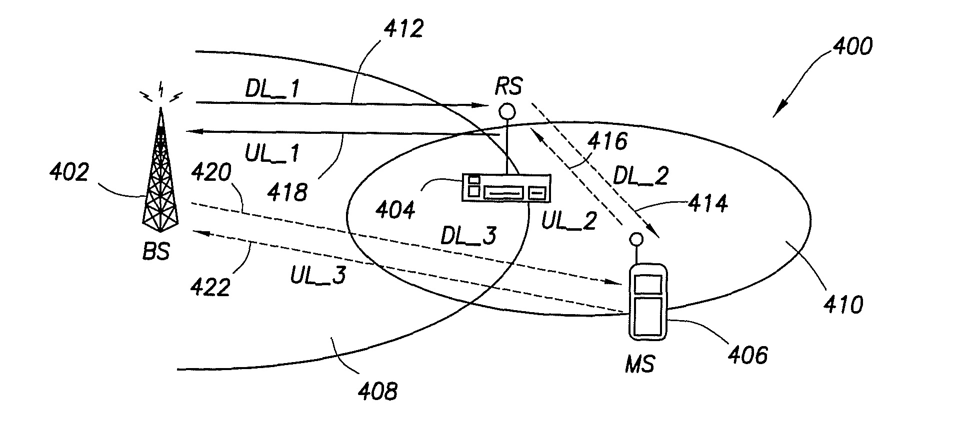
[0011] In a third embodiment, the present invention provides a method for allocating bandwidth in a multi-hop cellular communication network including a base station, a relay station, and at least one mobile station, by determining an initial amount of bandwidth to be allocated for the relay station, allocating a plurality of sub-carriers for the relay station, determining if a request has been received to change the allocation of sub-carriers, if a request has been received to change the allocation of sub-carriers, determining if the relay station has requested an allocation of at least one sub-carrier, and if the relay station has requested an allocation of at least one sub-carrier, selecting the at least one sub-carrier for allocation, if a request has been received to change the allocation of sub-carriers, determining if a channel quality value associated with the at least one mobile station has been received, and if the channel quality value has been received, selecting a sub-carrier associated with the received channel quality value; and allocating a fixed amount of bandwidth to the relay station including the at least one sub-carrier or the sub-carrier associated with the received channel quality value.

Problems solved by technology

The limitations of single hop cellular networks are known.
For example, the coverage of single hop cellular networks is limited by radio “dead spots” caused by interference from structures (e.g., buildings, etc.) located in the paths of the radiated signals.
Also, the coverage of these networks is limited by the transmit power of the MSs.
Significant increases in MS transmit power in single hop cellular networks increases signal interference, which decreases network capacity and throughput as a result.
Another limitation of single hop cellular networks is that their channel configurations are fixed.
Consequently, the channel configurations of conventional single hop cellular networks are not scalable.
Although standards and protocols have been approved that support the use of multi-hop cellular communication networks, a number of important technical problems need to be resolved before such networks can be implemented.

Method used


Image

  • Channel configuration and bandwidth allocation in multi-hop cellular communication networks
  • Channel configuration and bandwidth allocation in multi-hop cellular communication networks
  • Channel configuration and bandwidth allocation in multi-hop cellular communication networks

Examples


Embodiment Construction

[0019] With reference now to the figures,FIG. 1 is a simplified block diagram 100, which illustrates coverage in a multi-hop cellular network, in accordance with an example embodiment of the present invention. For this illustrative example, diagram 100 depicts a portion of a multi-hop cellular network, which includes a BS 102, a fixed relay station (FRS) 104, a mobile relay station (MRS) 106, and an MS 108. For example, the multi-hop cellular network depicted in FIG. 1 may be implemented in accordance with IEEE Standard 802.16-2004. BS 102 is shown communicating with MS 108 on a downlink via three link segments 110a through 110c (e.g., multiple links or multi-hops). For example, link segment 110a may be implemented with a wireline connection between BS 102 and FRS 104, and link segments 110b and 110c may be implemented as wireless connections between FRS 104 and MRS 106, and MRS 106 and MS 108, respectively. Note that the multi-hop, indirect routing of signals from BS 102 to MS 108 ...


PUM


Abstract

A multi-hop wireless communication network is disclosed, which includes a fixed communication unit, at least one mobile communication unit, and a relay communication unit. The relay communication unit is operable to relay a plurality of signals bi-directionally between the fixed communication unit and the at least one mobile communuication unit, by receiving a first signal on at least one of a dedicated sub-carrier and a dynamic sub-carrier in a first downlink channel segment from the fixed communication unit, and transmitting the received first signal to the at least one mobile communication unit on a dynamic sub-carrier in a second downlink channel segment. Also, the relay communication unit is operable to receive a second signal on a dynamic sub-carrier in a first uplink channel segment from the at least one mobile communication unit, and transmit the received second signal to the fixed communication unit on at least one of a dedicated sub-carrier and a dynamic sub-carrier in a second uplink channel segment. Also, the fixed communication unit can allocate bandwidth dynamically or in a fixed amount in the first downlink channel segment, the relay communication unit can allocate bandwidth dynamically in the second downlink channel segment based on at least one Quality of Service value received from the at least one mobile communication unit, the relay communication unit can allocate bandwidth dynamically for the at least one mobile communication unit in the first uplink channel segment, and the fixed communication unit can allocate bandwidth dynamically or in a fixed amount for the relay communication unit in the second uplink channel segment.

Description

CROSS-REFERENCE TO RELATED APPLICATIONS AND CLAIM FOR PRIORITY [0001] The present application is related to U.S. Provisional Patent Application No. 60 / 724,119, entitled “CHANNEL CONFIGURATION FOR THE MULTIHOP CELLULAR NETWORKS,” filed on Oct. 6, 2005, and U.S. Provisional Patent Application No. 60 / 724,019, entitled “EFFECTIVE BANDWIDTH ALLOCATION FOR THE MULTIHOP CELLULAR NETWORKS,” also filed on Oct. 6, 2005, which are assigned to the assignee of the present application. The subject matter disclosed in U.S. Provisional Patent Application No. 60 / 724,119 and U.S. Provisional Patent Application No. 60 / 724,019 is incorporated by reference into the present application as if fully set forth herein. The present application hereby claims priority, under 35 U.S.C. §119(e), to U.S. Provisional Patent Application No. 60 / 724,119 and U.S. Provisional Patent Application No. 60 / 724,019.FIELD OF THE INVENTION [0002] The invention relates to the telecommunications field, and more particularly, but ...

Claims


Application Information

Patent Timeline
Patent Type & Authority Applications(United States)
IPC IPC(8): H04Q7/24H04W28/20H04W88/04
CPCH04B7/15542H04B7/2606H04W28/20H04W72/00H04W72/0453H04W84/047H04W84/12H04W88/04H04B7/02H04B7/14H04B7/155H04L27/26
Inventor KOO, CHANGHOIRAJKOTIA, PURVA R.
Owner SAMSUNG ELECTRONICS CO LTD
Learn More