Electric rotating machine and manufacturing method of the same

Inactive Publication Date: 2007-04-12
HITACHI ENG & SERVICES CO LTD +1
View PDF10 Cites 2 Cited by
  • Summary
  • Abstract
  • Description
  • Claims
  • Application Information

AI Technical Summary

Benefits of technology

[0011] A first object of the present invention is to provide an electric rotating machine having a connecting line which is easily mounted with simple structure and favorable in operability, secures an insulating distance from an adjacent coil, absorbs thermal extension in an axial direction repeatedly occurring at each actuation and stoppage and an operating force caused by displacement in a radial direction due to a centrifugal force, and does not lead to a fatigue fracture.
[0012] Further, a second object of the present invention is to provide a manufacturing method of an electric rotating machine which suppresses temperature rise of a bending portion of a connecting line to prevent reduction in strength of a copper material of the connecting line, when connecting the connecting line in the electric rotating machine.
[0015] According to the present invention, since the connecting line having the bending portion, and the bottom surface of the rotor winding only have to be joined to each other, it is unnecessary to use an extra component or perform an extra attachment operation like the prior art, and it is possible to receive a centrifugal force by the bottom surface of the rotor winding. Further, since deformation in the axial direction and the radial direction can be absorbed by the bending portion of the connecting line, it becomes possible to absorb thermal extension in the axial direction repeatedly occurring at each actuation and stoppage of the electric rotating machine, and an operating force caused by displacement in the radial direction due to a centrifugal force. As a result, the deformation amount of the connecting line is suppressed, and a fatigue fracture is prevented.
[0016] In addition, according to the manufacturing method of the present invention, since it is possible to suppress temperature rise of the bending portion of the connecting line when connecting the connecting line in the electric rotating machine, reduction in strength of the copper material of the connecting line can be prevented.

Problems solved by technology

As described above, because the connecting line disclosed in U.S. Pat. No. 5,122,696 is has the shape which requires complicated assemble processing by using a single conductor which is not formed by stacking conductors, the connecting line is unfavorable in operability, and the space occupation rate of a lateral bar portion of one of the above described T shapes is large, so that an insulating distance between adjacent coils which differ in electric potential becomes small, for example.
Further, since the connecting line has a vertical bar of the above described T shape connected to the coil and the other one of the above described T-shaped conductors in combination, the connecting line itself becomes heavy, which makes the cause of the displacement in the axial direction and the radial direction.
In addition, if the coil surface on which the connecting line is placed is close to the rotor surface and therefor a space is small, it is difficult to install this complicated structure.

Method used


Image

  • Electric rotating machine and manufacturing method of the same
  • Electric rotating machine and manufacturing method of the same
  • Electric rotating machine and manufacturing method of the same

Examples


example 1

[0028] Hereinafter, a connecting line in an electric rotating machine according to an embodiment of the present invention will be described with reference to the drawings.

[0029]FIG. 8 shows a turbine generator as one example of the electric rotating machine, and the turbine generator is generally constructed by a rotor 1 which is formed by winding a rotor winding (not shown) on a rotor body part 1b fixed to a rotary shaft 1a, and a rotor 20 which is formed by winding a stator winding 20c on a stator core 20b fixed to a stator frame 20a.

[0030]FIG. 9 shows the rotor 1 of the turbine generator shown in FIG. 8. As shown in the drawing, the rotor 1 is constructed by the rotary shaft 1a and the rotor body part 1b which is fixed to the rotary shaft 1a and extends in an axial direction, and has a plurality of slots formed with a predetermined space in a circumferential direction from each other, a rotor winding 2 with a plurality of rotor conductors stacked and housed in the respective sl...

example 2

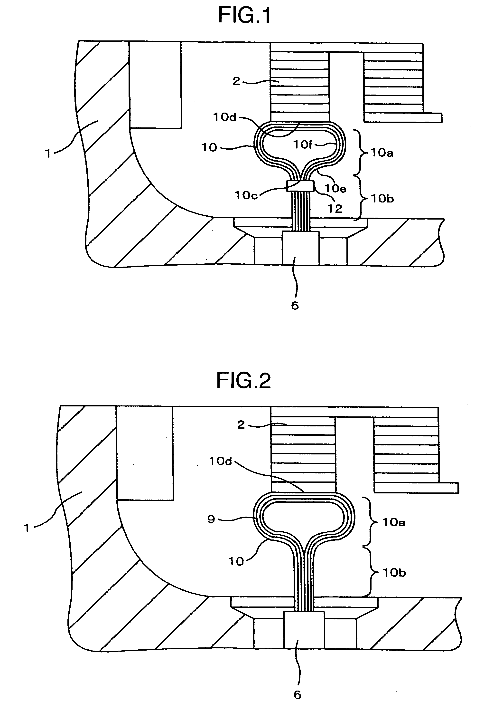
[0041]FIG. 2 shows an example in which the stopper 12 in the example shown in FIG. 1 is not provided, and all other components are the same as those in the example shown in FIG. 1.

[0042] In this example, although it is impossible to prevent the radial direction linear portion 10b of the connecting line from opening by the centrifugal force, it is possible not only to provide the effects of the above described example, but also to somewhat relieve the displacement in the outside diameter direction due to the centrifugal force acting on the connecting line 10 by the amount of the mass of the stopper 12 being eliminated.

example 3

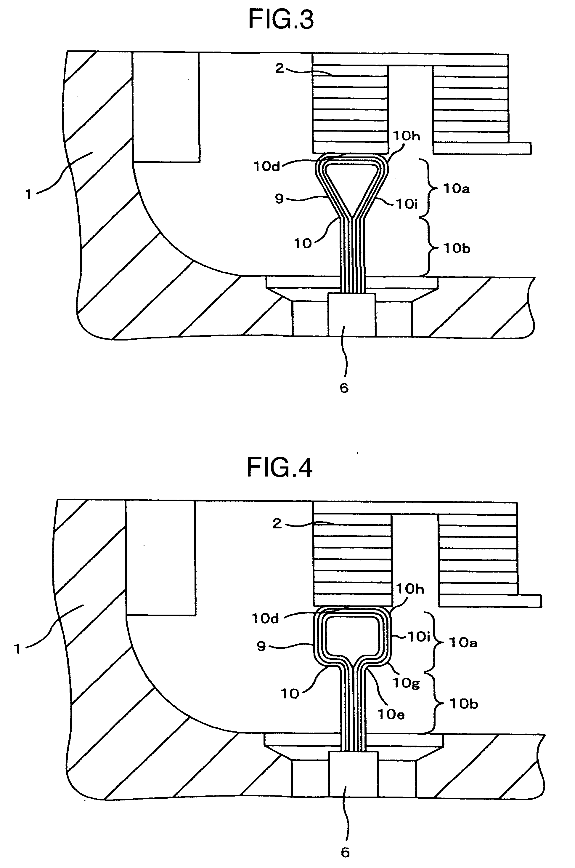
[0043]FIG. 3 shows an example in which the shape is made into a substantially inverted triangle by possibly shortening the bending portion 10a of the connecting line in the example shown in FIG. 2.

[0044] The bending portion 10a is formed into a triangular shape by a linear portion 10i in which the conductor plates extend in a V shape state from the radial direction linear portion 10b to branch into two routes with the same number (three in the drawing) of the conductor plates for each route, and by an axial direction linear portion 10d in which each of tip ends of the linear portion 10i extends inward in the rotor shaft direction via arc portions 10h to define one space.

[0045] In this example, it is possible not only to achieve the same effect as the above described example, but also to reduce the centrifugal force itself due to the own weight by making the mass of the connecting line 10 as small as possible, and therefore, the displacement in the outside diameter direction can be...


PUM


Abstract

A electric rotating machine includes a rotor winding constituting a part of a rotor, a conductor provided in a center portion in a radial direction of a rotor body for supplying electricity to the rotor winding from the outside, a leader drawn from the conductor to an outside diameter side, and a connecting line constructed by stacking a plurality of conductor plates to electrically connect the rotor winding and the leader. The connecting line consists of a radial direction linear portion which is straight in the radial direction on the leader side, and a bending portion which branches into two routes toward opposite directions to each other in a rotor shaft direction from the radial direction linear portion and has a linear portion formed at a part of the bending portion. The linear portion of the bending portion is joined to a bottom surface of the rotor winding.

Description

BACKGROUND OF THE INVENTION [0001] 1. Field of the Invention [0002] The present invention relates to an electric rotating machine and a manufacturing method thereof, and relates to an electric rotating machine such as a turbine generator and the like for example, which is preferable for those provide with a connecting line which connects a conductor for supplying electricity from the outside and an end portion of a rotor winding, and a manufacturing method thereof. [0003] 2. Description of Related Art [0004] A generator used in power generating equipment including a gas turbine or a steam turbine as a driving source generates electric power by mutual electromagnetic induction between a rotor and a stator. In general, a rotor winding is formed by a plurality of conductors wound thereon for producing an induction field, and a magnetic flux is generated by electrifying the winding. Accordingly, the rotor winding requires a conductor for supplying electricity from the outside of the gen...

Claims


Application Information

Patent Timeline
IPC IPC(8): H02K11/00H02K1/22
CPCH02K3/12Y10T29/49012H02K3/51
Inventor SEMBA, AKITOMIGOTO, FUMIHIKOENYAMA, JUICHI
Owner HITACHI ENG & SERVICES CO LTD
Why Eureka
Try Eureka