
Condiment dispenser

a condiment dispenser and dispenser body technology, applied in the field of condiment dispensers, can solve the problems of clogging of perforations, problems with prior flow control mechanisms, and several problems of condiment dispensers

Inactive Publication Date: 2007-04-12
SAHA ATANU
View PDF16 Cites 8 Cited by
  • Summary
  • Abstract
  • Description
  • Claims
  • Application Information

AI Technical Summary

Benefits of technology

[0009] According to example embodiment of the present invention, a dispersing element may be positioned at a spaced distance above and over the discharge chamber and in particular, above and over the dispensing outlet, although other configurations are possible. In this way, the discharge chamber and the dispersing element form a gapped outlet (dispensing gap). By positioning the dispersing element in this fashion, the dispersing element operates as a flow mechanism that controls the rate at which condiments are discharged from the discharge chamber and thereby from the condiment dispenser. Specifically, as the condiment dispenser is tilted or inverted in order to dispense condiments, the condiments enter the discharge chamber and subsequently exit the chamber through the dispensing outlet. As the condiments exit through the outlet, the condiments largely bounce up and against the dispersing element. As this occurs, the condiments largely deflect back into the discharge chamber, with only a controlled amount of the condiments subsequently passing through the dispensing gap and thereby from the condiment dispenser. As such, the dispersing element interferes with and deflects the flow of the condiments through the dispensing outlet, thereby controlling the rate at which the condiments are dispensed from the discharge chamber and more particularly, from the condiment dispenser. In addition, the dispersing element may also extend beyond the perimeter of the discharge chamber. In this way, once the condiments pass through the dispensing gap, the dispersing element causes the condiments to flow outward and around the dispersing element while exiting the condiment dispenser, thereby causing the condiments to disperse outward, assisting in the spreading of the condiments. As such, according to an embodiment of the present invention, the condiment dispenser avoids the use of perforations, which typically clog, in order to dispense and disperse condiments.
[0012] According to an example embodiment of the invention, the rotational dial for each flow control mechanism is configured to resistively rotate, for example, such that each dial can be individually moved to any flow position and thereafter retain that position. In this way, a user can individually configure each flow control mechanism to a desired setting and then dispense the condiments without the difficulty of trying to maintain the settings. Similarly, a user can individually configure each flow control mechanism to a desired setting and have each mechanism retain its respective setting between uses.

Problems solved by technology

These prior art condiment dispensers have several problems.
Condiments, such as salt, however, will often collect within the perforations causing the perforations to clog.
Problems also exist with prior flow control mechanisms.
Over time, the condiments can collect within the mechanisms causing the mechanisms to clog and become difficult to use.
These spring-activated mechanisms can be problematic for several reasons.
In addition, these spring activated mechanisms can be difficult to use given that a user must set and maintain the mechanisms at a desired setting while at the same time shaking the dispenser.
For condiment dispensers that hold multiple condiments, the difficulty increases when a user wishes to simultaneously dispense multiple condiments.
As such, the dispersing element interferes with and deflects the flow of the condiments through the dispensing outlet, thereby controlling the rate at which the condiments are dispensed from the discharge chamber and more particularly, from the condiment dispenser.
Similarly, as the dial is rotated so as to move the notched edge away from the pressing block, the tube naturally decompresses, thereby causing the size of the tube opening to increase back towards its original size and thereby increasing the flow of a condiment through the tube.
As result, the condiments are not able to collect upon the flow control mechanisms and interfere with the operation of the mechanisms.

Method used


Image

  • Condiment dispenser
  • Condiment dispenser
  • Condiment dispenser

Examples


Embodiment Construction

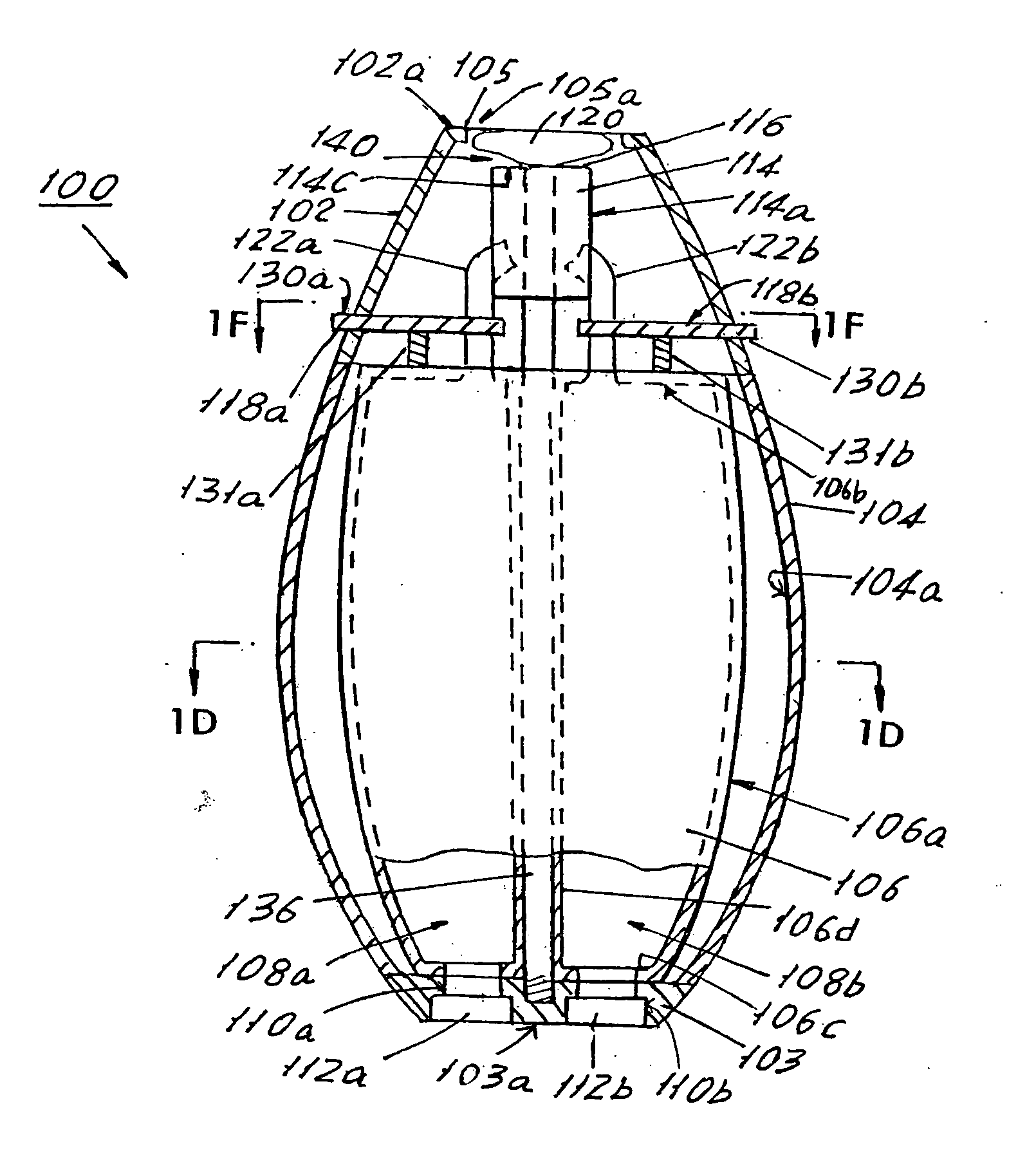
[0041] Referring to FIG. 1, there is illustrated a front view of an example condiment dispenser 100 according to the present invention. Condiment dispenser 100 includes a case 104, a cover 102 attached at the top side of a case 104, and a base 103 attached at the bottom side of case 104, for example, although dispenser 100 is not limited to this form. Case 104, cover 102, and base 103 may be formed from any suitable material known in the art (e.g., plastic, metal, wood, etc.) and may each be formed of the same material or of different materials, such as a combination of plastic and metal.

[0042] Referring now to FIG. 1A, there is shown a cross sectional side view of dispenser 100, with a portion of case 104, cover 102, and base 103 removed. As shown, dispenser 100 also includes a plurality of condiment chambers, such as two or more condiment chambers, like chambers 108a and 108b, disposed within case 104, for example. For description purposes, condiment dispenser 100 will be describ...


PUM


Abstract

A condiment dispenser includes one or more condiment chambers for holding condiments. Each condiment chamber is connected to a common discharge chamber or to a respective discharge chamber, the discharge chamber(s) having an outlet for dispensing condiments from the condiment chamber(s). Each connection may be formed through a respective tube. A flow control mechanism may control the flow from a condiment chamber to a discharge chamber. The mechanism may be a dial that is operable to compress and decompress the tube. The dial may move between numerous positions and retain any position between uses. A dispersing element may be positioned respective to the outlet of a discharge chamber to control the dispensing and dispersing of condiments. In an example operation, the flow control mechanism(s) are adjusted to a desired flow and the dispenser is inverted, causing condiment(s) to flow from the condiment chamber(s) and into the discharge chamber(s), where the condiments are dispensed and dispersed.

Description

BACKGROUND OF THE INVENTION [0001] 1. Field of the Invention [0002] The present invention relates to a condiment dispenser, and in particular, to a condiment dispenser with one or more condiment chambers, each with a flow control mechanism, and with one or more outlets through which the condiments are dispensed. [0003] 2. Description of the Art [0004] Condiment dispensers for holding and dispensing condiments, such as salt and pepper, are well known. Some condiment dispensers hold only a single condiment and other condiment dispensers hold and dispense multiple condiments. As is known, some condiment dispensers also include a flow control mechanism. These mechanisms assist a user in dispensing a desired amount of a condiment. When used on dispensers that hold multiple condiments, the flow control mechanisms may also allow a user to select and dispense one or more desired condiments while preventing the other condiments from being dispensed. [0005] These prior art condiment dispenser...

Claims


Application Information

Patent Timeline
Patent Type & Authority Applications(United States)
IPC IPC(8): A47G19/00B67D5/06B67D7/06
CPCA47G19/24
Inventor SAHA, ATANU
Owner SAHA ATANU
Learn More