
Hybrid vehicle drive control system

Inactive Publication Date: 2007-04-12
NISSAN MOTOR CO LTD
View PDF14 Cites 91 Cited by
  • Summary
  • Abstract
  • Description
  • Claims
  • Application Information

AI Technical Summary

Benefits of technology

[0012] The present invention is based on the idea that by reducing the connection of the second clutch to a slipping connection instead of disconnecting the second clutch completely, the torque fluctuations that occur when the engine is started by progressively connecting the first clutch can be prevented from being transmitted to the drive wheels while also resolving the problem of the output torque delivered to the drive wheels dropping to zero and causing the driver to feel an absence (loss) of torque during engine cranking. Thus, one object of the invention is to provide a hybrid vehicle engine start control device that realizes this idea in concrete form and resolves the aforementioned problem.
[0013] Another aspect of the present invention is to provide a hybrid vehicle engine start control device that can reliably resolve the aforementioned problem without being affected by variation of the relationship between the actual connection hydraulic pressure of the second clutch and a command value of the connection hydraulic pressure of the second clutch when the second clutch is connected in a slipping state while the engine is being started.

Problems solved by technology

As a result, there is the possibility that the output torque delivered to the drive wheels will drop to zero while the engine is being cranked and the driver will sense an absence of torque that feels odd.

Method used


Image

  • Hybrid vehicle drive control system
  • Hybrid vehicle drive control system
  • Hybrid vehicle drive control system

Examples


Embodiment Construction

[0031] Selected embodiments of the present invention will now be explained with reference to the drawings. It will be apparent to those skilled in the art from this disclosure that the following descriptions of the embodiments of the present invention are provided for illustration only and not for the purpose of limiting the invention as defined by the appended claims and their equivalents.

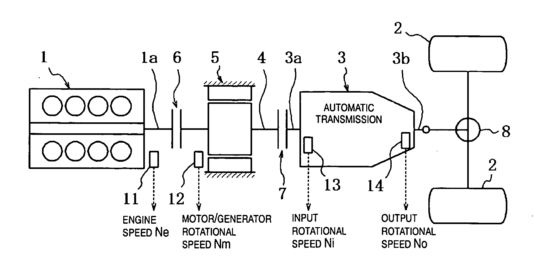
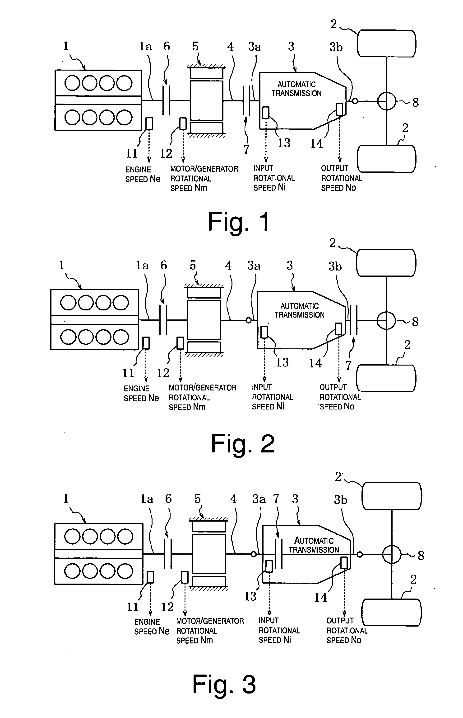
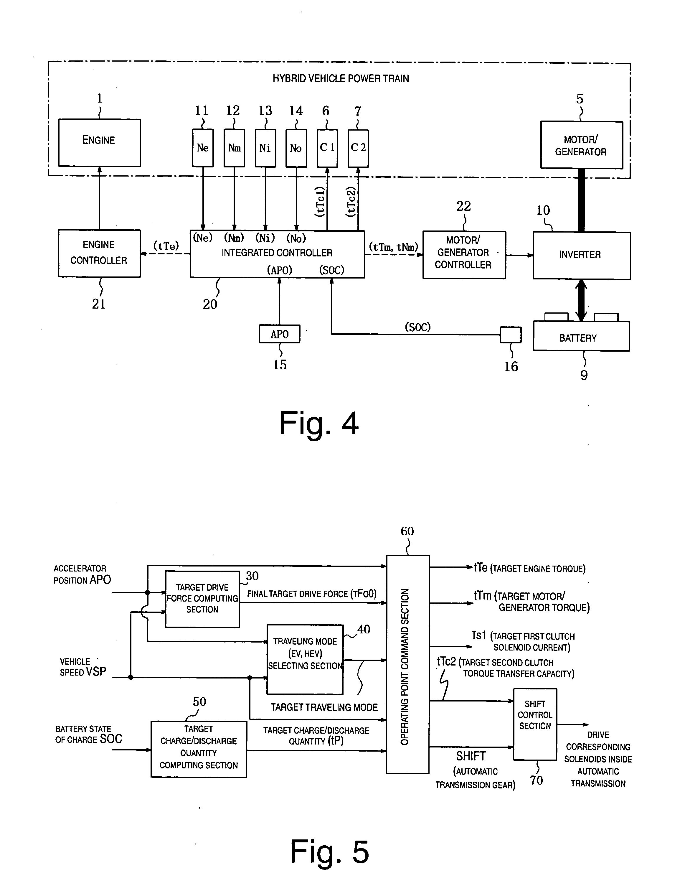
[0032] Referring initially to FIGS. 1 to 3, a front engine / rear wheel drive vehicle (rear wheel drive hybrid vehicle) is illustrated in each of the Figures in which each of the hybrid vehicles is equipped with a hybrid vehicle drive control system in accordance with one preferred embodiment of the present invention. Basically, the hybrid vehicles of FIGS. 1 to 3 illustrate three examples of alternate power trains of hybrid vehicles in which the hybrid vehicle drive control system in accordance with the present invention can be applied. In these examples, each hybrid vehicle includes, among other ...


PUM


Abstract

A hybrid vehicle drive control system selectively switches from an electric drive (EV) mode in which a first clutch is released and a second clutch is engaged, and a hybrid drive (HEV) mode in which both clutches are engaged. A slip control of the second clutch is executed when the first clutch is being connected to start the engine during switching from EV mode to HEV mode by controlling a torque transfer capacity of the second clutch to a required drive force, and by simultaneously increasing a motor / generator torque by an amount corresponding to a torque required to start the engine while maintaining a slipping state of the second clutch until connection of the first clutch is completed. Thus, a loss of torque is not felt by the driver and the shock is small when the engine is started during switching from EV mode to HEV mode.

Description

CROSS-REFERENCE TO RELATED APPLICATIONS [0001] This application claims priority under 35 U.S.C. §119 to Japanese Patent Application No. 2005-293248 filed on Oct. 6, 2005. The entire disclosure of Japanese Patent Application No. 2005-293248 is hereby incorporated herein by reference.BACKGROUND OF THE INVENTION [0002] 1. Field of the Invention [0003] The present invention relates to a hybrid vehicle drive control system of a hybrid vehicle having an electric drive (EV) mode a hybrid drive (HEV) mode. More particularly, the present invention relates to a hybrid vehicle drive control system for starting the engine when the vehicle shifts to the HEV mode as a result of output from the engine becoming necessary while the vehicle is traveling in the EV mode. [0004] 2. Background Information [0005] Various configurations have been proposed for hybrid vehicle drive control systems to be used in hybrid vehicles. One such hybrid drive system is presented in Japanese Laid-Open Patent Publicatio...

Claims


Application Information

Patent Timeline
IPC IPC(8): B60K6/00B60L50/10B60K6/48B60K6/54B60L50/16B60W10/02B60W10/06B60W10/08B60W20/00F16D48/02
CPCB60K6/48B60K6/547B60L2240/421B60L2240/441B60L2240/486B60W10/02B60W10/06B60W10/08B60W20/00B60W2510/0638B60W2510/081B60W2510/1015B60W2510/104B60W2710/025B60W2710/105Y02T10/6221Y02T10/6286Y02T10/642Y02T10/48Y02T10/40Y02T10/62Y02T10/64B60K2006/268F02N11/04F02N11/08B60W20/10B60W20/40
Inventor JOE, SHINICHIRO
Owner NISSAN MOTOR CO LTD
Learn More