Space Providing System and Information Exhibition System
a technology for providing systems and information exhibitions, applied in the field of space providing systems, can solve problems such as difficult replacement of information equipment and difficult redesign
- Summary
- Abstract
- Description
- Claims
- Application Information
AI Technical Summary
Benefits of technology
Problems solved by technology
Method used
Image
Examples
first embodiment
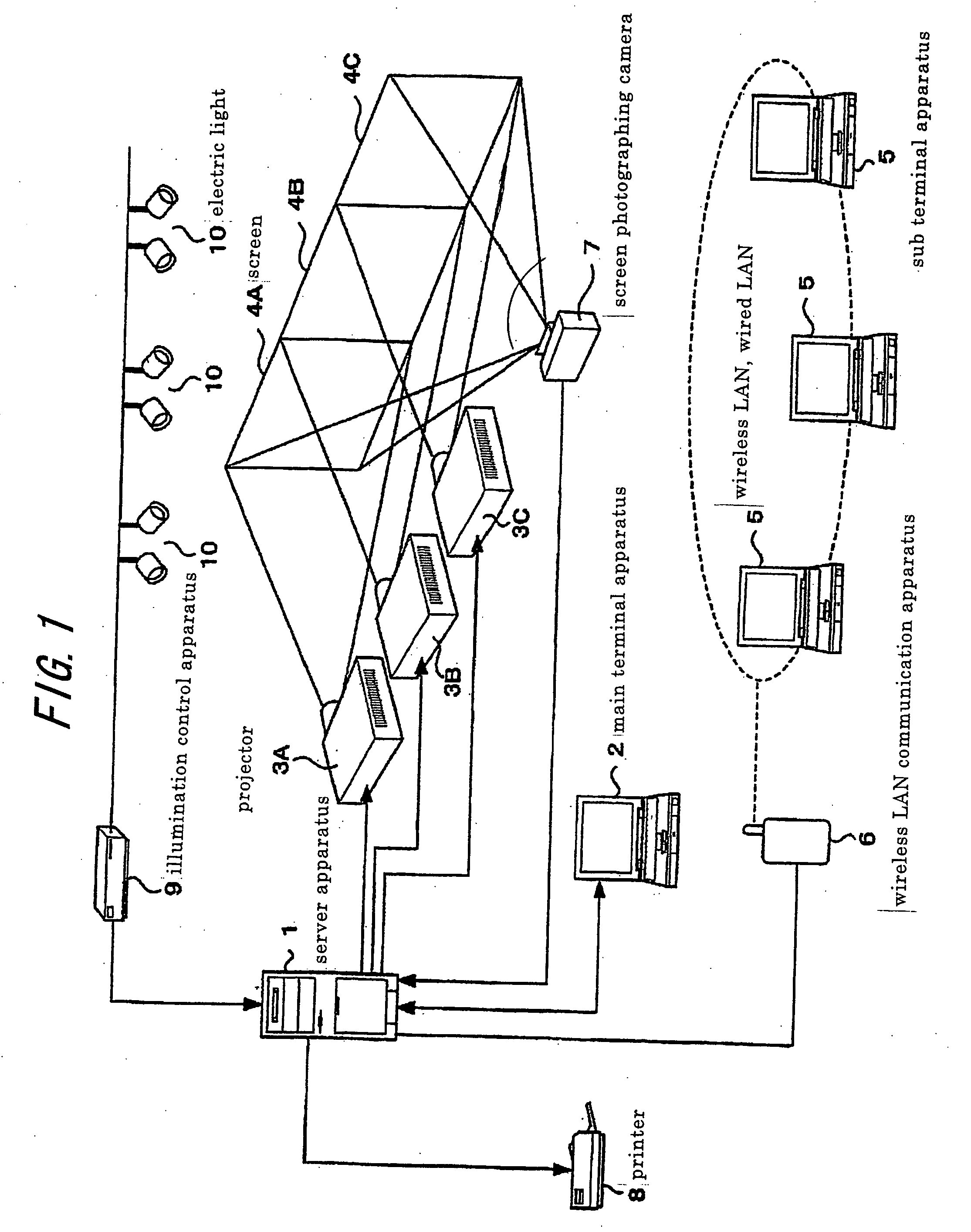
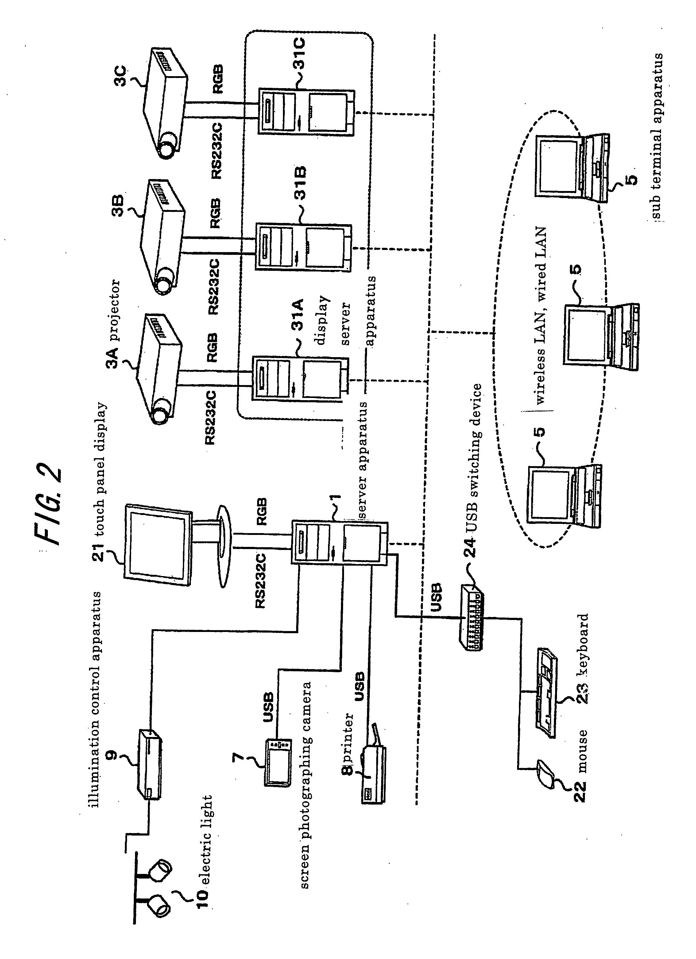
[0079] First, FIG. 5 shows as the process in which the main terminal apparatus 2 operated by the presenter displays an image through the projector 3, a process of displaying an image on the desktop of the main terminal apparatus 2 operated by the presenter directly through the projector 3 and a process of capturing the image displayed by the projector 3 in response to a participant's operation of the sub terminal apparatus 5.
[0080] After login to the server apparatus 1 is started by the main terminal apparatus 2 in step S3 and the login is accepted by the server apparatus 1 in step S15, a request for image projection is transmitted to the display server apparatus 31 by the main terminal apparatus in step S4. Upon receiving the request for image projection, the display server apparatus 31 transmits a request for image projection to the projector 3 in step S22. In response to the request, the projector 3 displays an image by projection in step S32.
[0081] On the other hand, after logi...
second embodiment
[0084]FIG. 6 shows, as the process in which the main terminal apparatus 2 operated by the presenter displays an image through the projector 3, a process of displaying an image based on image information that has been stored previously through the projector 3 upon a presenter's operation of the main terminal apparatus 2 and a process of capturing the image displayed by the projector 3 in response to a participant's operation of the sub terminal apparatus 5. In FIG. 6, the process steps that are the same as those in FIG. 5 are designated by the same reference signs.
[0085] After login to the server apparatus 1 is started by the main terminal apparatus 2 in step S3 and the login is accepted by the server apparatus 1 in step S15, a request for projection of previously stored image information is transmitted to the server apparatus 1 by the main terminal apparatus 2 in step S5. In response to the request, the server apparatus 1 starts to send the stored file in step S1OA. The display serv...
third embodiment
[0087]FIG. 7 shows, as the process in which the main terminal apparatus 2 operated by the presenter displays an image through the projector 3, a process of displaying an image through the projector 3 by uploading a file of an image from the main terminal apparatus 2 operated by the presenter and a process of capturing the image displayed by the projector 3 in response to a participant's operation of the sub terminal apparatus 5. In FIG. 7, the process steps that are the same as those in FIG. 5 are designated by the same reference signs.
[0088] After login to the server apparatus 1 is started by the main terminal apparatus 2 in step S3 and the login is accepted by the server apparatus 1 in step S15, a file for presentation is uploaded to the server apparatus 1 by the main terminal apparatus 2 in step S6. Then, the server apparatus 1 starts, in step SLOB, to forward the uploaded file. The display server apparatus 31 receives the file and executes it in step S26, whereby an image is dis...
PUM
 Abstract
Description
Claims
Application Information
 - R&D
- Intellectual Property
- Life Sciences
- Materials
- Tech Scout
- Unparalleled Data Quality
- Higher Quality Content
- 60% Fewer Hallucinations
Browse by: Latest US Patents, China's latest patents, Technical Efficacy Thesaurus, Application Domain, Technology Topic, Popular Technical Reports.
© 2025 PatSnap. All rights reserved.Legal|Privacy policy|Modern Slavery Act Transparency Statement|Sitemap|About US| Contact US: help@patsnap.com


