Transponder Unit

a transponder unit and unit body technology, applied in the field of transponder units, can solve the problems of inability to adapt to changing external conditions, instability and dimensional accuracy cannot be guaranteed, and installation adjustment errors have negative effects on the operational reliability and efficiency of the transponder, so as to influence the stability of the housing and reliably utilize the

Inactive Publication Date: 2007-03-29
HARTING MITRONICS
View PDF9 Cites 6 Cited by
  • Summary
  • Abstract
  • Description
  • Claims
  • Application Information

AI Technical Summary

Benefits of technology

[0019] In addition, the introduction of a dielectric into the space between the upper housing side and the lower housing side advantageously influences the stability of the housing as well as the radiation characteristic of the transponder.
[0020] The realization of the housing with corresponding installation aids such as bores, slots and form-fitted bonding surfaces allows a simple installation on arbitrary objects. Consequently, the transponder is suitable for use on all installation surfaces and can also be reliably utilized in the industrial environment.

Problems solved by technology

In this context, it is disadvantageous that installation and adjustment errors have negative effects on the operational reliability and efficiency of the transponder.
If different materials are joined together, the stability and dimensional accuracy also cannot be ensured under significant temperature fluctuations and external mechanical stresses because components with different properties are connected to one another.
Furthermore, adaptations to changing external conditions can only be realized by modifying the components, wherein a new construction is required in many instances.

Method used


Image

  • Transponder Unit
  • Transponder Unit
  • Transponder Unit

Examples


Embodiment Construction

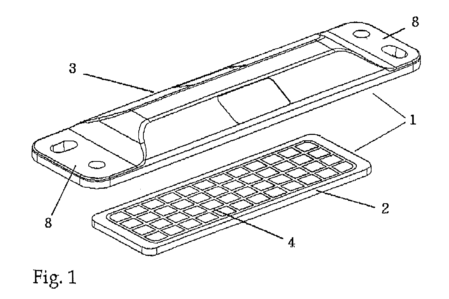
[0026]FIG. 1 shows a transponder unit 1 with a lower housing part 2 and an upper housing part 3. The upper housing part features installation aids 8 in the form of bores and / or slots that simplify the attachment of the transponder to arbitrary objects.

[0027] The grounding surface 4 on the lower housing part 2 consists of intersecting metal strips such that a grid is formed. However, the grounding surface could also be realized in a planar fashion.

[0028] The lower housing part 2 is fitted into a corresponding annular recess 10 in the upper housing part 3 in the form of a complete unit and preferably welded thereto such that a seamless transition is realized between the laterally protruding surfaces of the mounting aids 8 and the lower housing part 2.

[0029] However, no electrically conductive connections are produced between the upper housing side and the lower housing side.

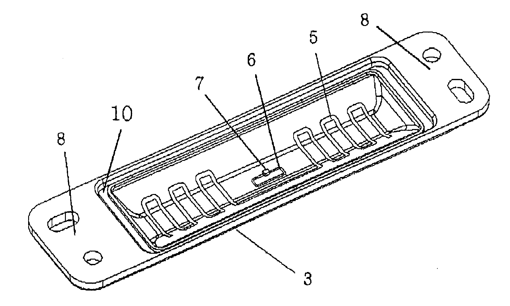
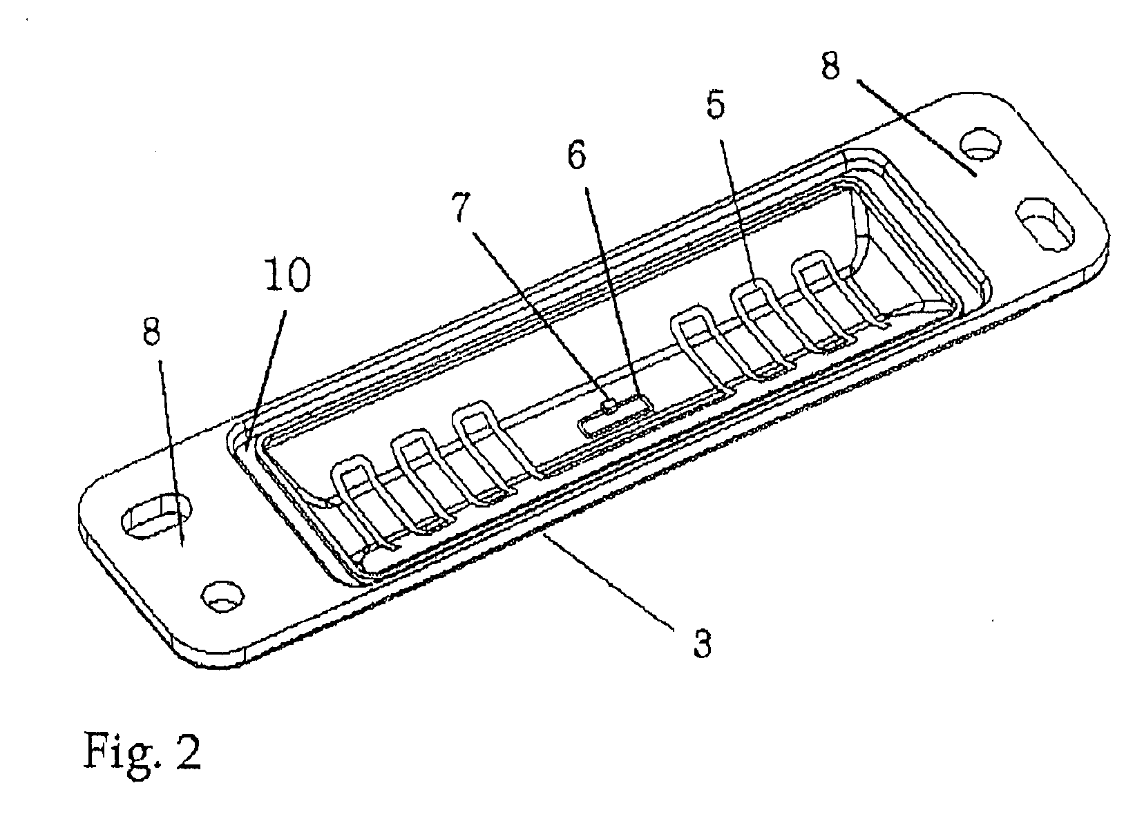
[0030]FIG. 2 shows a perspective representation of the inner side of the upper housing part 3 of the transpo...


PUM


Abstract

In order to realize a cost-effective production of a transponder in an RFID system that is intended for the identification of merchandise, the invention proposes a two-part housing with an upper housing part and a lower housing part, wherein the lower housing part is provided with a grounding surface and an antenna with a transponder IC is spaced apart from and arranged above this grounding surface.

Description

FIELD OF THE INVENTION [0001] The invention pertains to a transponder unit in a hermetically sealed housing that consists of a lower housing part and an upper housing part. BACKGROUND OF THE INVENTION [0002] The development of Radio Frequency Identification Systems (RFID) has advanced significantly in the last few years. RFID systems are used, e.g., for the identification of merchandise in department stores as well as in the fields of logistics and control or automation technology. In accordance with the industrial environment, these systems are subject to strict requirements with respect to reliability and ease of operation. A broad variety of designs is available. These systems are produced in the form of printed labels, ISO cards, key fobs, etc. [0003] RFID systems consist of a transmission module (transponder) with stored data, wherein the transponder is composed of one or more integrated circuits (transponder ICs), an antenna and other passive components. [0004] The system furt...

Claims


Application Information

Patent Timeline
Patent Type & Authority Applications(United States)
IPC IPC(8): H04Q5/22G06K7/00
CPCG06K19/07749G06K19/07779G06K19/07775
Inventor BARALDI, LUCAEGGIMANN, RETOHEHLGANS, JORGPATRY, CHRISTIAN
Owner HARTING MITRONICS
Why Eureka
Try Eureka