
Patient transport apparatus

a technology for transporting equipment and patients, applied in the directions of wheelchair/patient conveyancing, transportation and packaging, nursing beds, etc., can solve the problems of staff members being off the schedule for weeks and even months, unable to simply convey patients, and currently available solutions that are insufficient, so as to facilitate linear travel, facilitate the extraction of patients, and facilitate the recovery of fallen patients

Inactive Publication Date: 2007-03-29
WILDER WILLIAM A
View PDF20 Cites 29 Cited by
  • Summary
  • Abstract
  • Description
  • Claims
  • Application Information

AI Technical Summary

Benefits of technology

[0010] A patient transport apparatus is shown and described. The patient transport apparatus of the present invention is articulated and sized to fit within the door opening of virtually all vehicles. Further, the patient transport apparatus uses a height-adjustable seat that is aligned with the vehicle seat to allow for simplified extraction of the patient from the vehicle. The height-adjustable seat lowers to just above ground height making the recovery of a fallen patient easier. A set of casters allows omni-directional travel of the patient transport apparatus for precise placement and a pair of primary motion wheels makes linear travel easier while providing a minnimal turning radius.
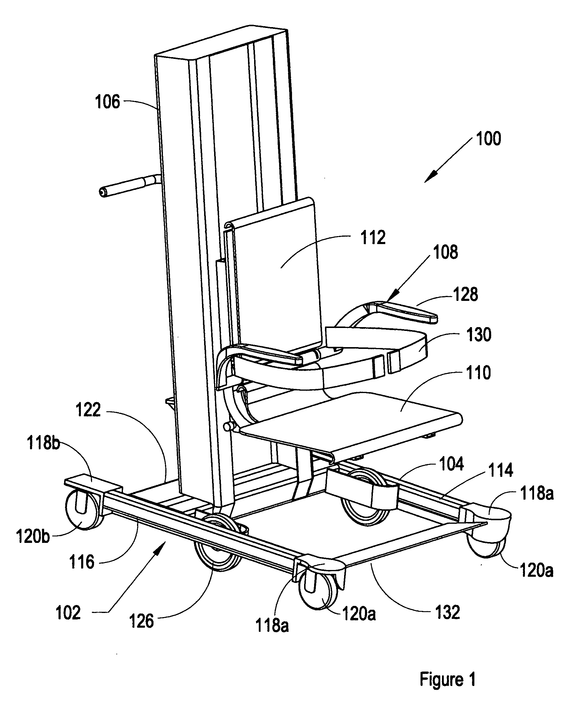
[0011] The major components of the patient transport apparatus include a frame having a base and a chair support, and a chair having a seat and a back. The base provides stability and a framework for the wheel system. The chair support is substantially orthogonal to the base and carries the chair. The chair is moveable vertically along the substantial height of the chair support. The seat is sized to accommodate a patient of large girth. The backrest is narrower than the seat. The chair is reclined to provide greater comfort for the patient and to position the patient in a manner where gravity assists in holding the patient in the desired position.
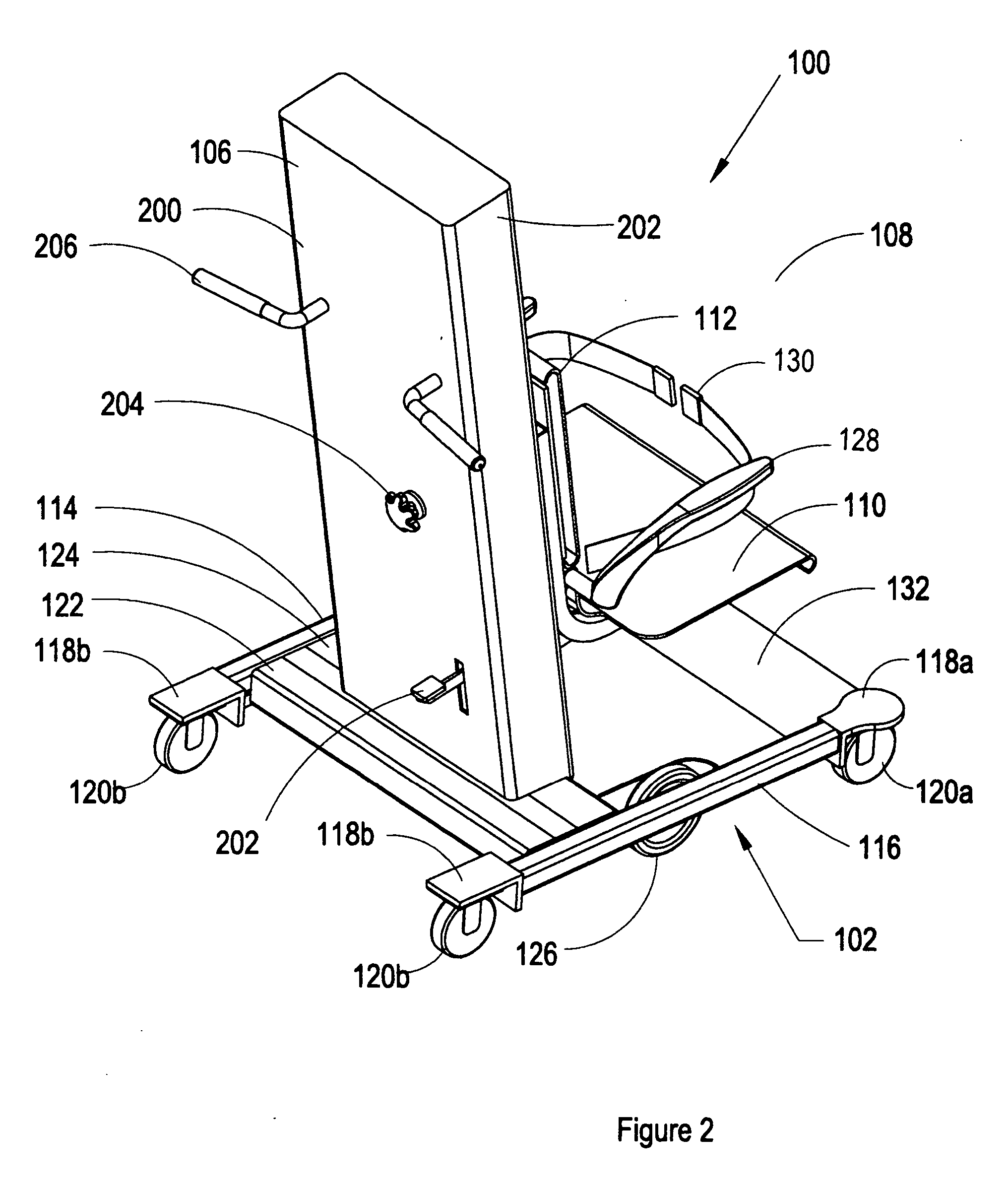
[0012] The frame is fabricated from a rigid material rated to withstand the applied forces without bending or incurring other damage. The base includes a first side rail and a second side rail. The first side rail and the second side rail are connected by one or more cross-members that are substantially perpendicular to the side rails. One function of the cross-members is to maintain the position of the first side rail relative to the second side rail. The distance between the side rails is selected to provide lateral stability. In addition, the cross-members provide a mounting point for the chair support.
[0013] A plurality of free-moving wheels, such as orbital casters, provide the patient transport apparatus with omni-directional movement for precise positioning and control. In addition, a plurality of primary motion wheels are provided for efficiently moving the patient transport apparatus over longer linear distances and for making turns with a substantially zero-degree turn radius.
[0015] The chair support is a substantially vertical pillar that serves as a guide and support for the vertically-moving chair. The chair support is designed to withstand the frontal torque and the load requirements of the patient transport apparatus. Positioned at the second end of the chair support and distal from the base is a control box. The control box encloses the drive control system. The drive control system actuates the vertical movement of the chair. A simple user interface allows the operator to control the up and down movement of the chair.

Problems solved by technology

Although healthcare providers work to provide services to heavier patients by purchasing new equipment and educating staff members; however, the reality remains that it has become increasingly difficult to simply convey patients.
While healthcare providers and healthcare equipment vendors have attempted to address this growing challenge, the currently available solutions appear insufficient when looking at the growing number of staff injuries and lost work time that is associated with conveying patients.
Moving heavier patients is one significant contributor to work related injuries.
A staff member may be off the schedule for weeks and even months due to such injuries.
In addition to the risk to the staff members, there are concerns on the patient side as well.
Like the staff member, the patient also runs a risk of injury during transport as a result of being lifted, pulled, pushed, slid from, or transferred into, out of, or between conveyances.
While dealing with the very real, difficult, and unfortunate problem of transporting heavier patients, the patient's dignity is often compromised.
It is difficult for patients to maintain dignity when ten men are called to move them.
One of the most problematic areas in patient transport is the loading and unloading of a patient from a vehicle.
The confines of the automobile, the obstruction of the door, and the low seat height make patient assistance a difficult task.
Conditions such as these are especially likely to result in embarrassment or injury.
For example, it is not uncommon to inadvertently set the patient on the ground during this type of transfer, which at best only diminishes the dignity of the patient, and embarrasses the staff member.

Method used


Image

  • Patient transport apparatus
  • Patient transport apparatus
  • Patient transport apparatus

Examples


Embodiment Construction

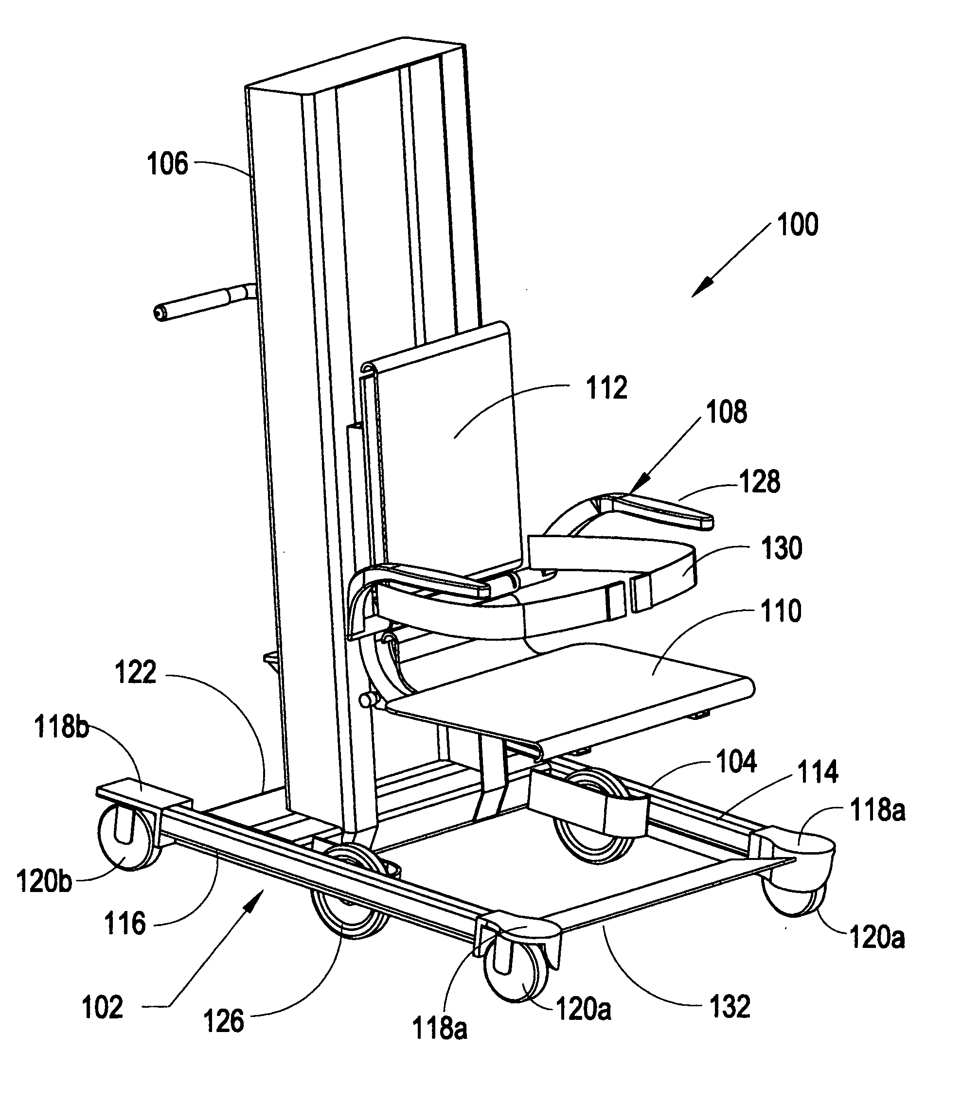
[0032] A patient transport apparatus is described and shown at 100 in the figures. The patient transport apparatus 100 of the present invention is articulated and sized to fit between the body and the open door of virtually all vehicles. Further, the patient transport apparatus 100 uses a height-adjustable seat that is aligned with the vehicle seat to allow for simplified extraction of the patient from the vehicle. The height-adjustable seat lowers to just above ground height making the recovery of a fallen patient easier. A set of casters allows omni-directional travel of the patient transport apparatus 100 for precise placement and a pair of primary motion wheels makes linear travel easier while providing a minimal turning radius.

[0033]FIG. 1 is a front perspective view of the patient transport apparatus 100. The major components of the patient transport apparatus 100 include a frame 102 having a base 104 and a chair support 106, and a chair 108 having a seat 110 and a back 112. ...


PUM


Abstract

A patient transport apparatus. The patient transport apparatus of the present invention is articulated and sized to fit between the body and the open door of virtually all vehicles. Further, the patient transport apparatus uses a height-adjustable seat that is aligned with the vehicle seat to allow for simplified extraction of the patient from the vehicle. The height-adjustable seat lowers to just above ground height making the recovery of a fallen patient easier. A set of casters allows omni-directional travel of the patient transport apparatus for precise placement and a pair of primary motion wheels makes linear travel easier while providing a turning radius substantially approaching zero.

Description

CROSS-REFERENCE TO RELATED APPLICATIONS [0001] Not Applicable. STATEMENT REGARDING FEDERALLY SPONSORED RESEARCH OR DEVELOPMENT [0002] Not Applicable. BACKGROUND OF THE INVENTION [0003] 1. Field of Invention [0004] The invention relates to a patient transport apparatus. [0005] 2. Description of the Related Art [0006] Over the last thirteen years, healthcare providers have witnessed marked change in patient numbers as well as patient needs. Thirteen years ago, a patient weighing 400 pounds or more was a rarity. These patients were extraordinary cases and not an everyday assignment. Today, dealing with patients weighing 400 pounds or more is a daily way of life. At any given time, any healthcare facility is likely to have admitted at least one patient who weighs 600 pounds or more. Although healthcare providers work to provide services to heavier patients by purchasing new equipment and educating staff members; however, the reality remains that it has become increasingly difficult to s...

Claims


Application Information

Patent Timeline
Patent Type & Authority Applications(United States)
IPC IPC(8): A61G7/10
CPCA61G5/043A61G5/1059A61G7/1011A61G3/063A61G7/1046A61G7/1048A61G7/1059A61G7/1019
Inventor WILDER, WILLIAM A.
Owner WILDER WILLIAM A
Learn More