
Sensor Web

a technology of sensors and webs, applied in the field of sensors webs, can solve the problems of loss of any further data from the environment, the inability of redundant sensors to provide additional information, and the limited application of devices, so as to achieve better and more accurate environmental awareness

Inactive Publication Date: 2007-03-15
CALIFORNIA INST OF TECH
View PDF17 Cites 13 Cited by
  • Summary
  • Abstract
  • Description
  • Claims
  • Application Information

AI Technical Summary

Benefits of technology

The Sensor Web system provides enhanced environmental awareness by transforming scalar information into vector information, anticipating and tracking phenomena, and adapting to site-specific needs, while minimizing infrastructure costs and power consumption.

Problems solved by technology

However, a single point failure mode in these sensors will result in loss of any further data from the environment.
Redundant sensors can be provided to avoid this problem, but the redundant sensors typically will not provide additional information, but rather simply act as prevention against failure.
These devices are quite limited in their application.
For example, these devices typically do not provide non-local awareness of spatio-temporal phenomena and therefore cannot anticipate or track phenomena, such as a plume moving through the environment.
This technology however, also has several drawbacks.
The existing platforms already have high utilization rates for multiple tasks and the ability to redirect this capability may be limited.
In addition, a limitation to the loiter / observation times of airborne and space based platforms exists due to orbital patterns, refueling needs and, in some instances, crew and operator limitations—particularly when observing transient or sporadic phenomena.
There are also sensing and sensitivity limitations imposed via physics (i.e. sensing inside building / structures, subterranean, etc.).
These systems also prevent raw data from being in the hands of end-users, instead requiring expensive and time-consuming post-data analysis before it is in readable form.

Method used


Image

  • Sensor Web
  • Sensor Web
  • Sensor Web

Examples


Embodiment Construction

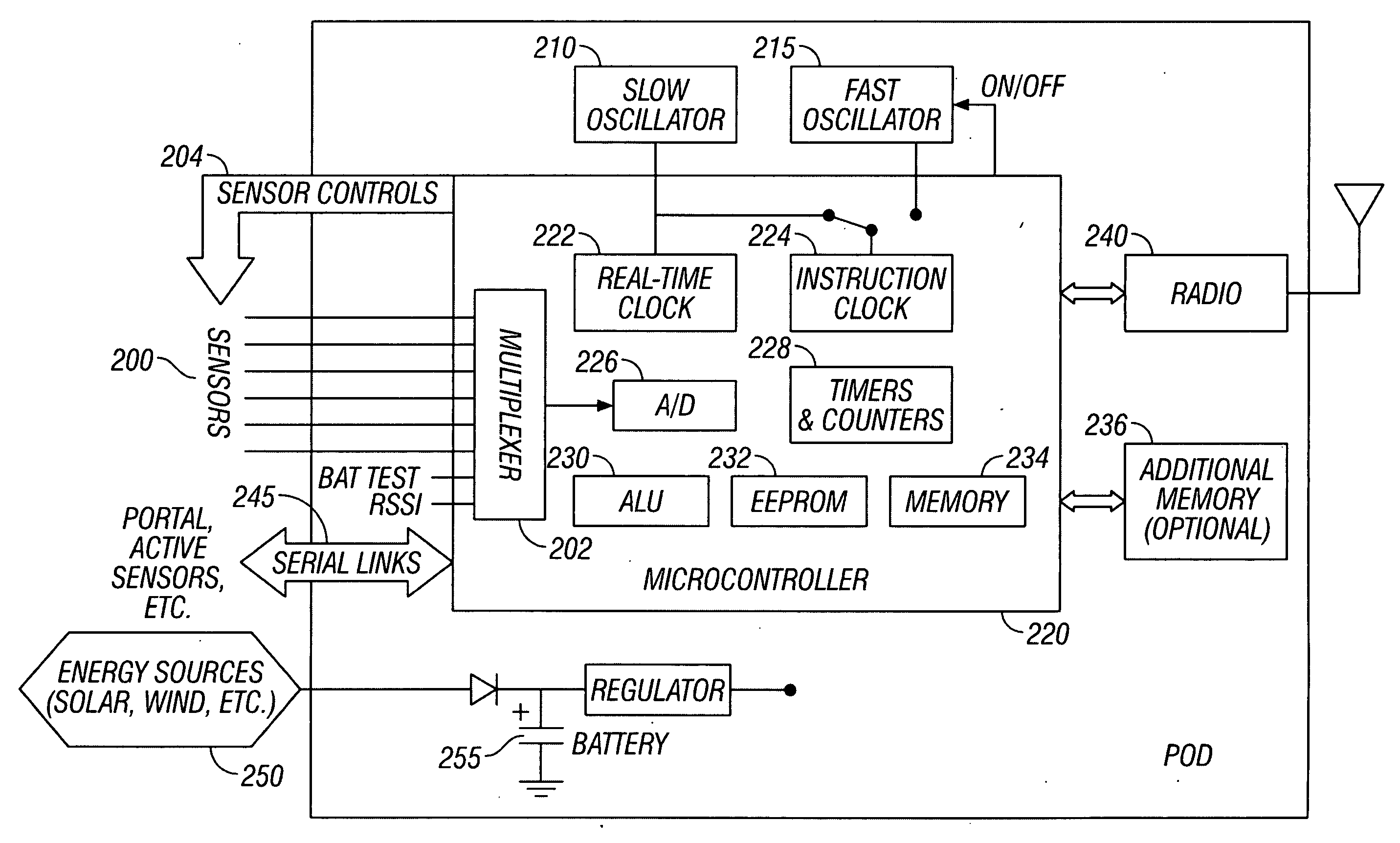
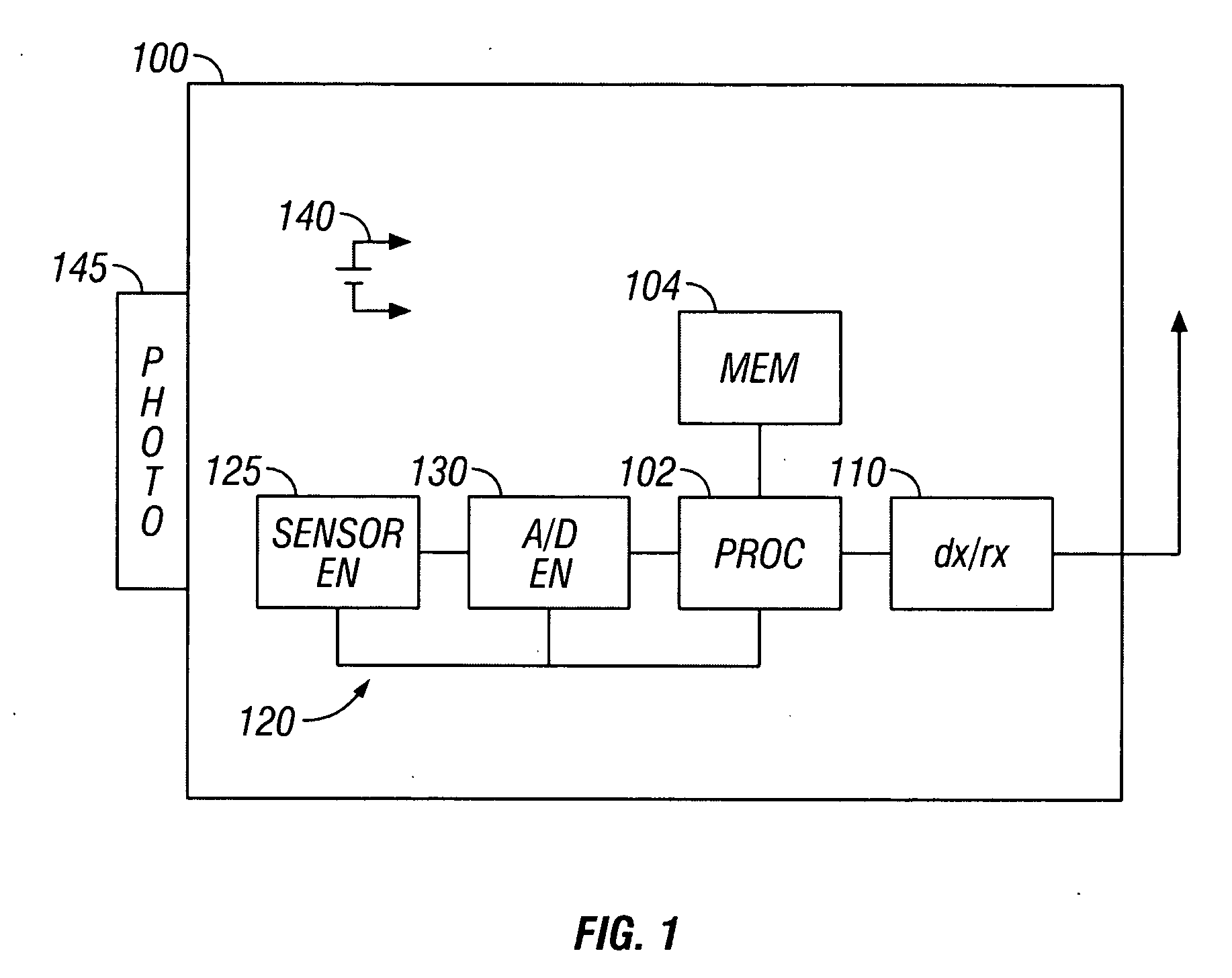
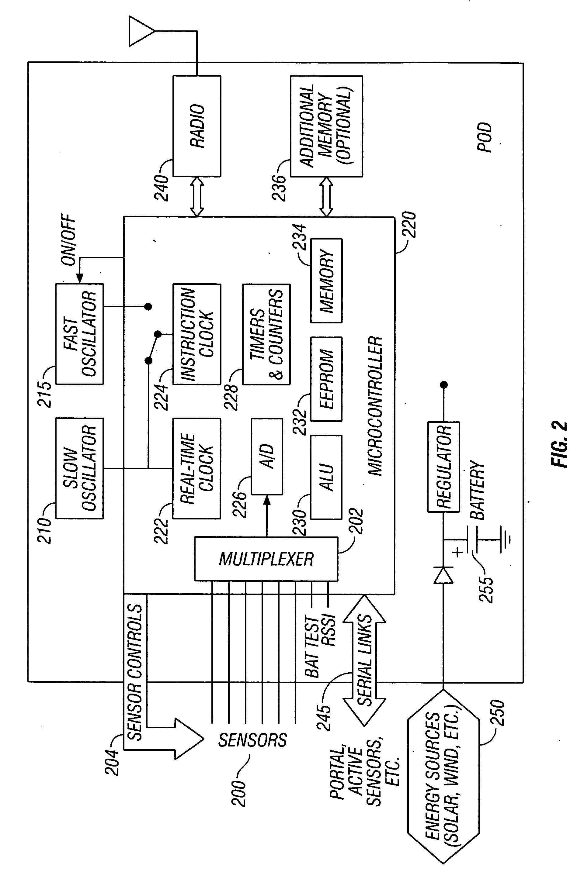
[0027] The present application describes a number of Sensor Web nodes, which are typically wirelessly interconnected and communicate to form a macroinstrument from the groups of nodes. Each “node” on a Sensor Web can be either a specific individual pod, or another sensor web itself. The nodes can communicate amongst themselves. The communication causes distribution of information throughout the instrument as a whole. Throughout the description that follows, it is assumed that the nodes are pods, but it should be understood that the nodes can also be webs themselves.

[0028] Much as the intelligence in the brain is a result of the myriad of connections between dendrites, the Sensor Web effectively forms a macrointelligence as a result of the distributed information with the collection of pods reacting and adapting to their environment. The synergy between the pods provides information that is more than would be available from any of the pods individually. For example, the sensors coll...


PUM


Abstract

A Sensor Web formed of a number of different sensor pods. Each of the sensor pods include a clock which is synchronized with a master clock so that all of the sensor pods in the Web have a synchronized clock. The synchronization is carried out by first using a coarse synchronization which takes less power, and subsequently carrying out a fine synchronization to make a fine sync of all the pods on the Web. After the synchronization, the pods ping their neighbors to determine which pods are listening and responded, and then only listen during time slots corresponding to those pods which respond.

Description

CROSS-REFERENCE TO RELATED APPLICATIONS [0001] This application is a divisional application of U.S. application Ser. No. 10 / 682,308, filed Oct. 8, 2003, which claims priority under 35 U.S.C. 119(e)(1) to U.S. provisional application Nos. 60 / 417,375, filed Oct. 9, 2002 and 60 / 426,317, filed Nov. 14, 2002.BACKGROUND AND SUMMARY [0002] Sensing of parameters can be used to determine information about the environment for many purposes. A sensor can be used to detect conditions which require action. Rapid analysis of this information can enable better and more accurate environmental awareness. [0003] Different ways of obtaining such information are known. [0004] A single point sensor system provides monitoring of only a single location in space. Such devices can be used to detect multiple phenomena in different sensory environments. However, a single point failure mode in these sensors will result in loss of any further data from the environment. Redundant sensors can be provided to avoid...

Claims


Application Information

Patent Timeline
Patent Type & Authority Applications(United States)
IPC IPC(8): G06F19/00A47J43/042A47J43/046G01D5/48G06KG06K1/00H04J3/06
CPCG01D21/00H04W84/18H04W40/24H04J3/0641H04W56/001
Inventor DELIN, KEVIN A.JACKSON, SHANNON P.
Owner CALIFORNIA INST OF TECH
Learn More