
Variable speed stent delivery system

a stent and variable speed technology, applied in the field of medical devices, can solve the problems of increasing the deployment speed and the relative slowness of achieve the effect of slowing the initial stent deployment speed and increasing the deployment speed

Active Publication Date: 2007-03-15
CR BARD INC
View PDF99 Cites 150 Cited by
  • Summary
  • Abstract
  • Description
  • Claims
  • Application Information

AI Technical Summary

Benefits of technology

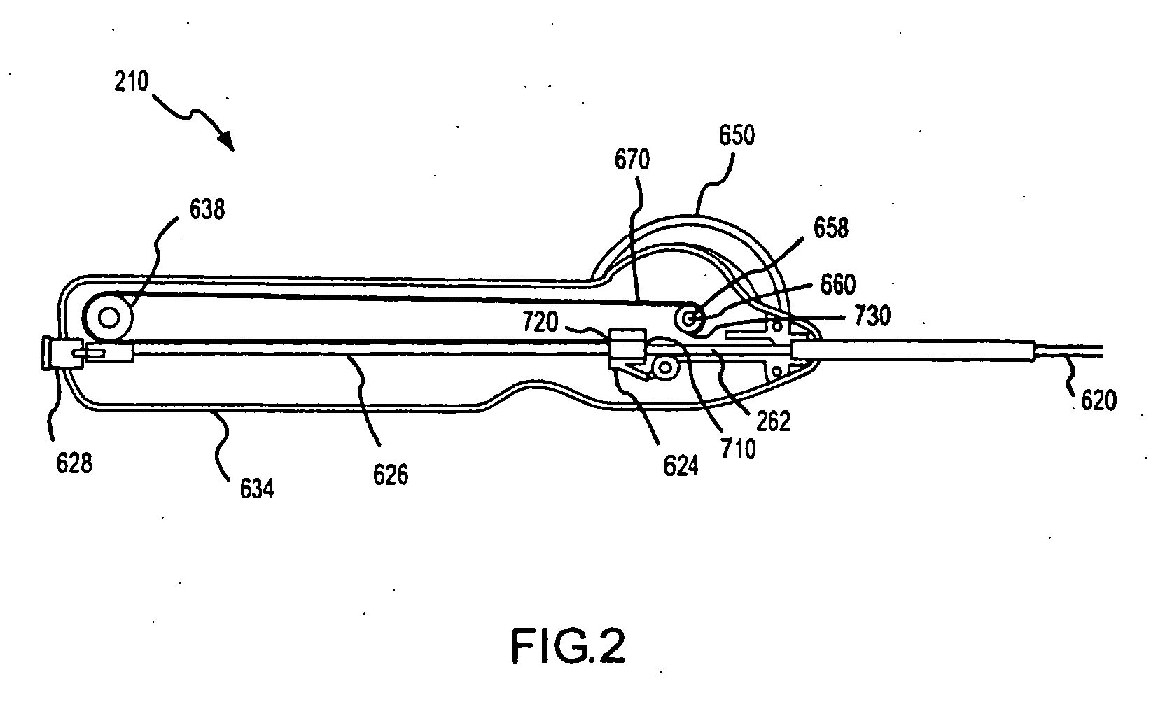
[0026] According to one aspect of the invention, the retraction speed increases from the first position to the second position of the connector element substantially continuously. The connector element is typically moved along a linear path and the retraction speed can be measured as an increasing linear velocity of the connector element and attached sheath. The variable speed mechanism in one embodiment includes a slide rod mating with an opening or passageway in the connector element so that the connector element is able to slide along the length of the slide rod from its first to its second position. The mechanism further includes a take up pulley and a drive belt or belt segment attached at a first end to the connector element and at a second end to the take up pulley. A knob or other user input device is provided in the deployment assembly for allowing a user to apply a motive force or input rotation rate. The knob is connected to the take up pulley to rotate the pulley at the input rotation rate. When the pulley rotates, the drive belt is wound onto a contact surface of the take up pulley to move the connector element. The retraction speeds are varied or increased with the rotation of the pulley with the drive belt being wound not just on the pulley but also upon previously wound portions or thicknesses of the drive belt. As the overall diameter of the take up pulley increases, the linear velocity of the drive member, i.e., the retraction speed of the connector element and sheath and deployment speed of the stent, also increases for a single input rotation rate. As a result, the delivery system provides a relatively slow initial stent deployment speed to position the stent and, then, continuously increasing deployment speed to rapidly deploy the remaining portions of the stent.

Problems solved by technology

As a result, the delivery system provides a relatively slow initial stent deployment speed to position the stent and, then, continuously increasing deployment speed to rapidly deploy the remaining portions of the stent.

Method used


Image

  • Variable speed stent delivery system
  • Variable speed stent delivery system
  • Variable speed stent delivery system

Examples


Embodiment Construction

[0031] The present invention is directed to a device, and associated method, for delivering stents at a continuously variable speed. More particularly, the variable speed stent delivery system of the present invention is configured for delivering self-expanding stents at speeds that continuously increase from a relatively slow initial deployment speed to a significantly faster final deployment speed. The continuously variable speeds or continuously increasing speeds with the deployed length of the stent facilitates accurate positioning and initial impingement of the deployed portions of the stent against the inner wall of a body lumen while also improving the efficiency of the procedure by reducing the time to deploy the later portions of the stent and reducing risks of the stent being dislodged as the stent is rapidly deployed once positioned.

[0032] In general, delivery systems for self-expanding stents include a catheter assembly and a handle or control handle. A proximal end of ...


PUM


Abstract

A delivery system for deploying a medical device, such as a stent, at increasing deployment speed is described. The system comprises a catheter comprising a catheter shaft, a retractable sheath slidably mounted on the catheter shaft, and the device in a compressed state sandwiched between the shaft and sheath. A control handle is included with a housing and knobs for a user to apply a rotary or other force to retract the sheath. The sheath is attached to a slider that is mounted on a slide rod and attached to a drive belt. A take up pulley is provided in the housing and connected to the belt input knob, so that the pulley turns when the knob is turned. The belt is attached to the pulley so that the drive is wound onto the rotating pulley. As the belt winds upon the pulley, the overall outside diameter of the pulley increases, thereby increasing the deployment speed.

Description

CROSS REFERENCE TO A RELATED PATENT APPLICATION [0001] Priority is herewith claimed under 35 U.S.C. §119(e) from co-pending Provisional Patent Application No.: 60 / 709,314, filed Aug. 17, 2005, entitled “VARIABLE SPEED STENT DELIVERY SYSTEM”. The disclosure of this Provisional Patent Application is incorporated by reference herein in its entirety.FIELD OF THE INVENTION [0002] The present invention relates, in general, to medical devices, e.g., expandable stents, and, more particularly, to an enhanced method of delivering medical devices into a body lumen, such as a blood vessel, at a delivery rate or speed that varies from a relatively slow initial delivery speed during initial positioning to increasingly faster delivery speed along the remaining length of the stent. BACKGROUND OF THE INVENTION [0003] Atherosclerosis is the deposition of fatty plaques on the luminal surface of arteries, which in turn causes narrowing of the cross-sectional area of the artery. Ultimately, this deposit...

Claims


Application Information

Patent Timeline
IPC IPC(8): A61F2/06
CPCA61F2/95A61F2002/9517A61F2/966A61F2/9517
Inventor RANDALL, MICHAELFULKERSON, JOHN
Owner CR BARD INC
Learn More