Mobile communication system, and base transceiver station apparatus and mobile station apparatus used in mobile communication system
- Summary
- Abstract
- Description
- Claims
- Application Information
AI Technical Summary
Benefits of technology
Problems solved by technology
Method used
Image

Examples
first embodiment
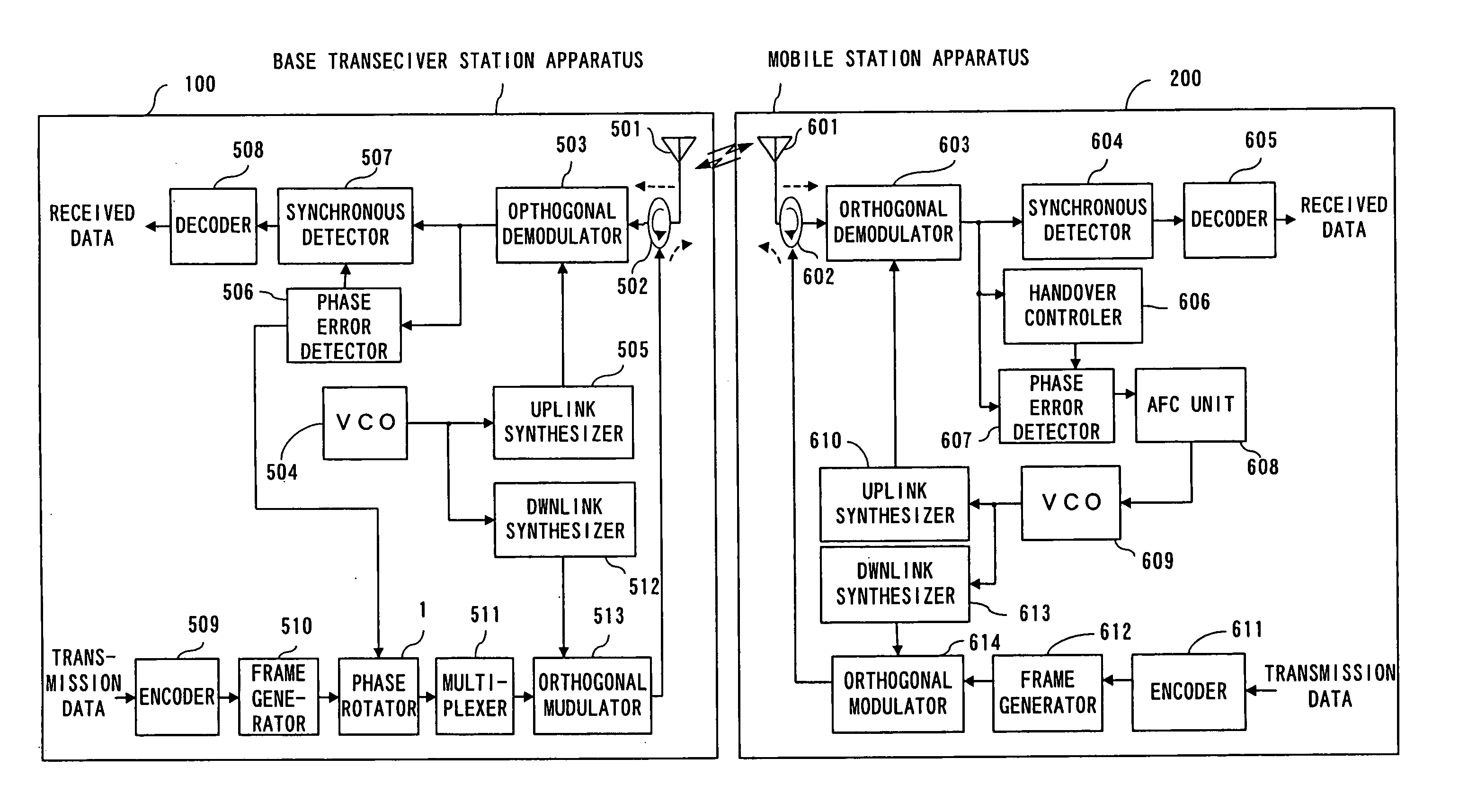
[0053]FIG. 4 is a diagram showing a configuration of a mobile communication system of the In FIG. 4, a base transceiver station apparatus 100 comprises a phase rotator 1 in addition to the antenna element 501, the separator (circulator) 502, the orthogonal demodulator 503, the Voltage Control Oscillator (VCO) 504, the uplink frequency synthesizer 505, the phase error detector 506, the synchronous detector 507, the decoder 508, the encoder 509, the frame generator 510, the multiplexer 511, the downlink frequency synthesizer 512, and the orthogonal modulator 513.
[0054] The received signal input via the antenna element 501 is down-converted into a base band signal in the orthogonal demodulator 503 after being separated from the transmission signal by the circulator 502. Here, the VCO 504 generates a reference clock, and the uplink frequency synthesizer 505 generates a periodic wave with a predetermined frequency unique to the system (a sinusoidal wave, for example) from the reference ...
second embodiment
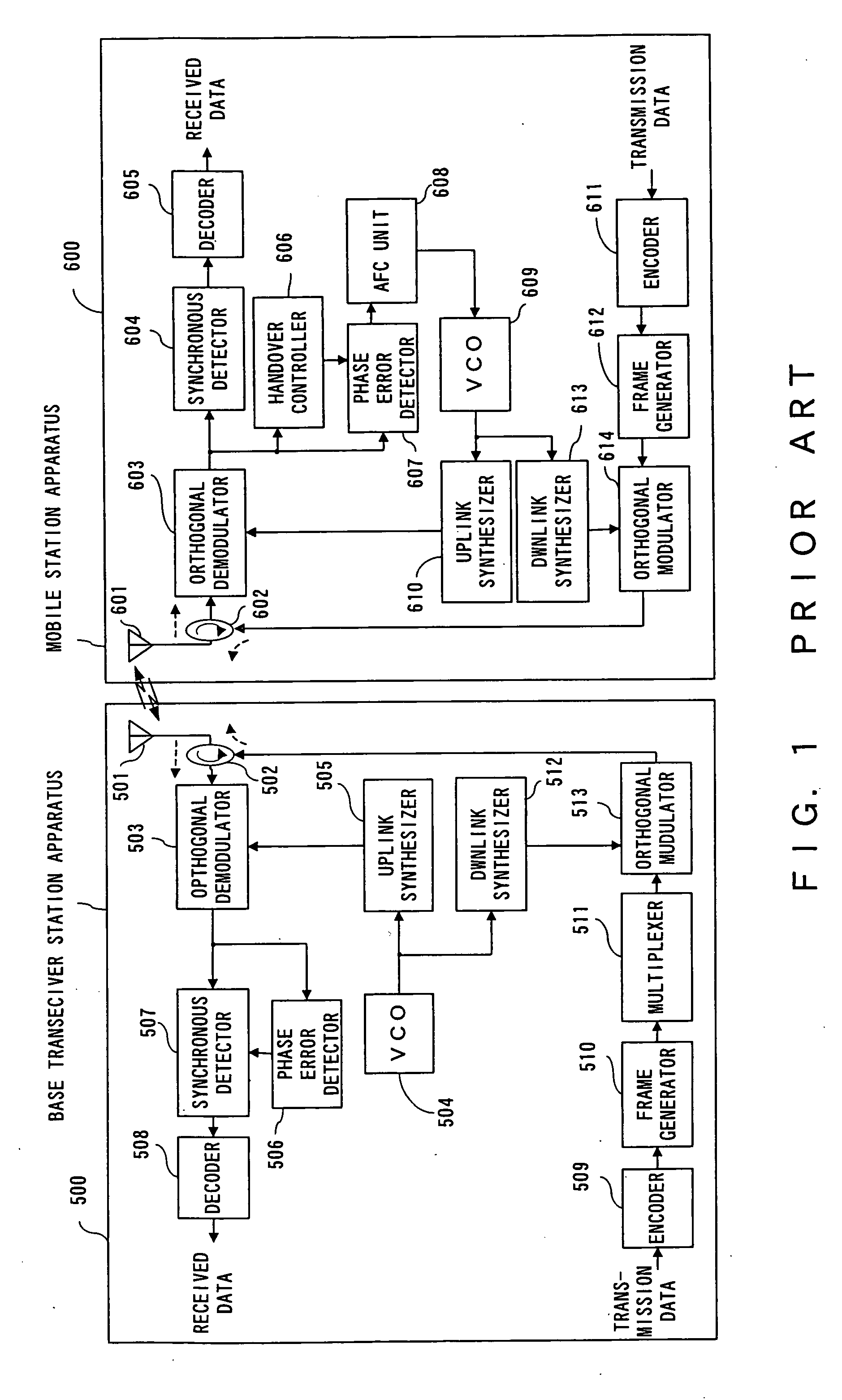
[0082]FIG. 9 is a diagram showing a configuration of the mobile communication system of the Compared with the conventional base transceiver station apparatus 500 shown in FIG. 1, a frequency control (FC) command generator 11 is provided in a base transceiver station apparatus 110 shown in FIG. 9. A frame generator 12 comprises a function for writing in a frequency control command generated by the FC command generator 11 in a prescribed region, in addition to functions comprised in the frame generator 510 shown in FIG. 1.
[0083] A mobile station apparatus 210, in addition to the conventional configuration shown in FIG. 1, comprises a downlink VCO 21, an uplink VCO 22, and a frequency controller 23 for controlling the uplink VCO 22 in accordance with the frequency command transmitted from the base transceiver station. During reception of the frequency command, the frequency of the uplink VCO 22 is controlled independently of the downlink VCO 21. The downlink VCO 21 is basically the sa...
seventh embodiment
[0114]FIG. 12 is a diagram explaining a sequence of the frequency control. The sequence is performed in the third through the seventh embodiment explained later.
[0115] First, downlink data of slot #N is transmitted from the base transceiver station to the mobile station. The downlink data is received by the mobile station at timing delayed by the propagation delay (=Tp) of the downlink propagation path from the transmission timing of the base transceiver station. The mobile station transmits the uplink data of slot #N at a timing delayed by a prescribed system-specific time (=TUL-DL) from the reception timing of the downlink data. The base transceiver station receives the uplink data of slot #N at timing delayed by propagation delay (=Tp) of the uplink propagation path from the transmission timing of the mobile station. Then, the phase error detector 506 in the base transceiver station calculates the frequency offset of the received wave by the time correlation of the pilot signal i...
PUM
 Abstract
Description
Claims
Application Information
 - Generate Ideas
- Intellectual Property
- Life Sciences
- Materials
- Tech Scout
- Unparalleled Data Quality
- Higher Quality Content
- 60% Fewer Hallucinations
Browse by: Latest US Patents, China's latest patents, Technical Efficacy Thesaurus, Application Domain, Technology Topic, Popular Technical Reports.
© 2025 PatSnap. All rights reserved.Legal|Privacy policy|Modern Slavery Act Transparency Statement|Sitemap|About US| Contact US: help@patsnap.com