Temperature Compensated and Self-Calibrated Current Sensor using Reference Magnetic Field
a current sensor and reference magnetic field technology, applied in the field of current sensor, can solve the problems of measurement errors, difficult to achieve or maintain calibration with this approach, large weight of current transformer, etc., and achieve low weight, low cost, and revenue accuracy measurement
- Summary
- Abstract
- Description
- Claims
- Application Information
AI Technical Summary
Benefits of technology
Problems solved by technology
Method used
Image
Examples
first embodiment
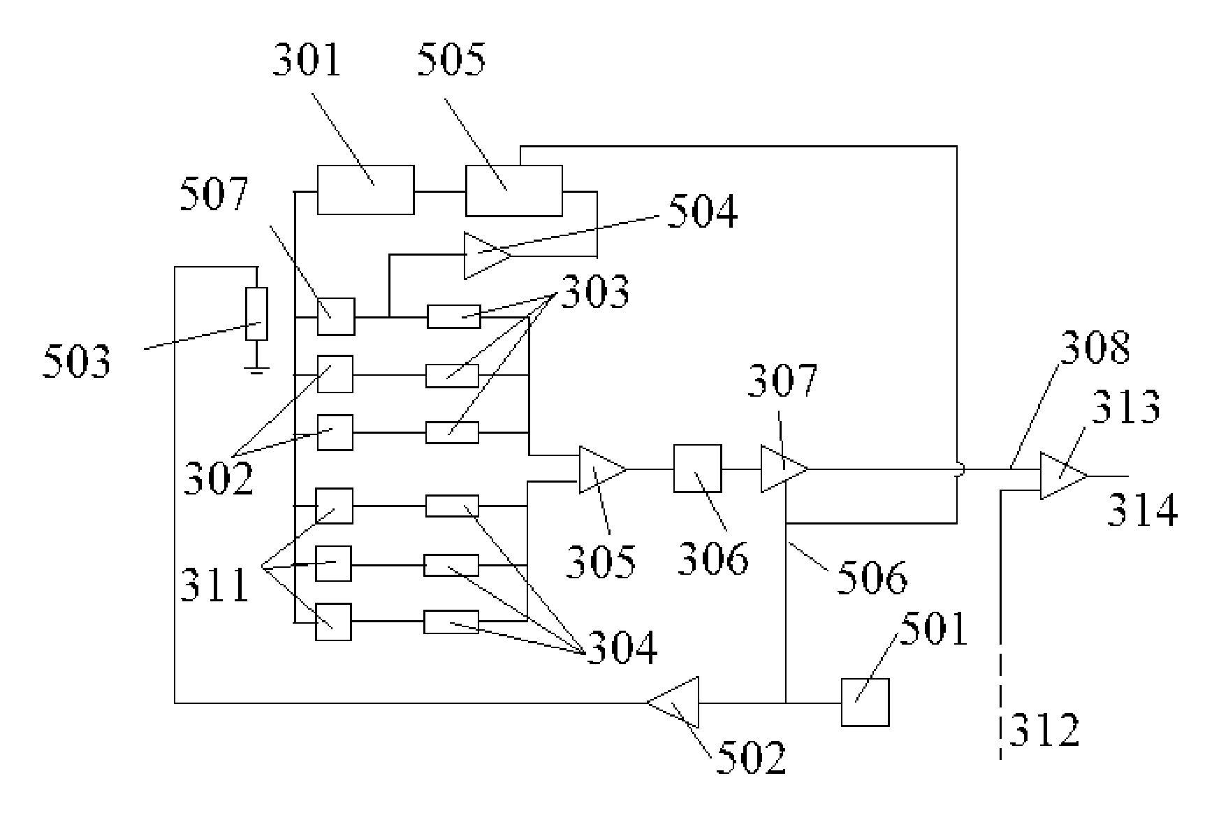
[0067] temperature compensation is shown in FIG. 3. The ambient temperature of the printed circuit board is detected by temperature sensor 309 and used to generate a voltage that is proportional to temperature, or a digital number that is proportional to temperature. The error voltage is generated in signal processor 310 using an analog amplifier, or it may be generated by a digital look-up table stored in an electronic memory that is addressed by a number representing the ambient temperature, and provides a digital number that is converted to an analog voltage using a conventional digital-to-analog converter. The error voltage controls a voltage regulator 301 that generates the power supply voltage for all of the magnetic field sensors. As the temperature of the printed wiring board varies, the sensitivity of the magnetic field sensors varies. For example, the output signal may vary by +3% over a temperature change of 100 degrees C. This is compensated by an equal and opposite vari...
third embodiment
[0069] In temperature compensation shown in FIG. 5A and 5B, a magnetic field is generated in the vicinity of one or more of the magnetic field sensors. The magnetic field can be a DC field created by a permanent magnet 509 in close proximity to one magnetic field sensor 507, or a DC or AC field generated by an electromagnet such as a solenoid 503. The magnetic field sensor 507 should be selected to have a temperature dependence that is substantially the same as the average temperature dependence of the entire array of magnetic field sensors. If a DC magnetic field is used, then the current sensor can only be used to measure AC currents. If an AC magnetic field is used, then the current sensor can be used to measure DC and AC currents. The magnitude of the extra magnetic field in the region surrounding the magnetic field sensor is kept as stable as possible. For the permanent magnet 509, this is achieved by selecting the permanent magnet material to have thermally stable properties, ...
fourth embodiment
[0070] In temperature compensation shown in FIG. 6A, 6B and 6C, a separate magnetic field sensor 604 is placed inside of a stable solenoid coil 603 that is in turn driven by a constant current generator. The magnetic field generated by the solenoid coil 603 is an AC field. The solenoid coil 603 and the magnetic field sensor 604 are oriented in such a way that the direction of the generated and detected magnetic field is substantially perpendicular to the sensitivity axis of the magnetic field sensors 302 already present on the printed circuit board 606. The magnetic field sensor 604 should be selected to have a temperature dependence that is substantially the same as the average temperature dependence of the entire array of magnetic field sensors. The magnitude of the extra magnetic field in the region surrounding the magnetic field sensor 604 is kept as stable as possible. For the solenoid 603, a stable magnetic field is achieved by constructing the solenoid coil mandrel from stabl...
PUM
 Abstract
Description
Claims
Application Information
 - R&D
- Intellectual Property
- Life Sciences
- Materials
- Tech Scout
- Unparalleled Data Quality
- Higher Quality Content
- 60% Fewer Hallucinations
Browse by: Latest US Patents, China's latest patents, Technical Efficacy Thesaurus, Application Domain, Technology Topic, Popular Technical Reports.
© 2025 PatSnap. All rights reserved.Legal|Privacy policy|Modern Slavery Act Transparency Statement|Sitemap|About US| Contact US: help@patsnap.com


