
Portable paint booth

a paint booth and portability technology, applied in the field of mobile booth systems, can solve the problems of not providing an optimal covering, affecting the appearance of the booth, and consuming a lot of time, and achieve the effect of lowering the pressur

Inactive Publication Date: 2007-03-15
ANTAYA BRUCE C
View PDF15 Cites 41 Cited by
  • Summary
  • Abstract
  • Description
  • Claims
  • Application Information

AI Technical Summary

Benefits of technology

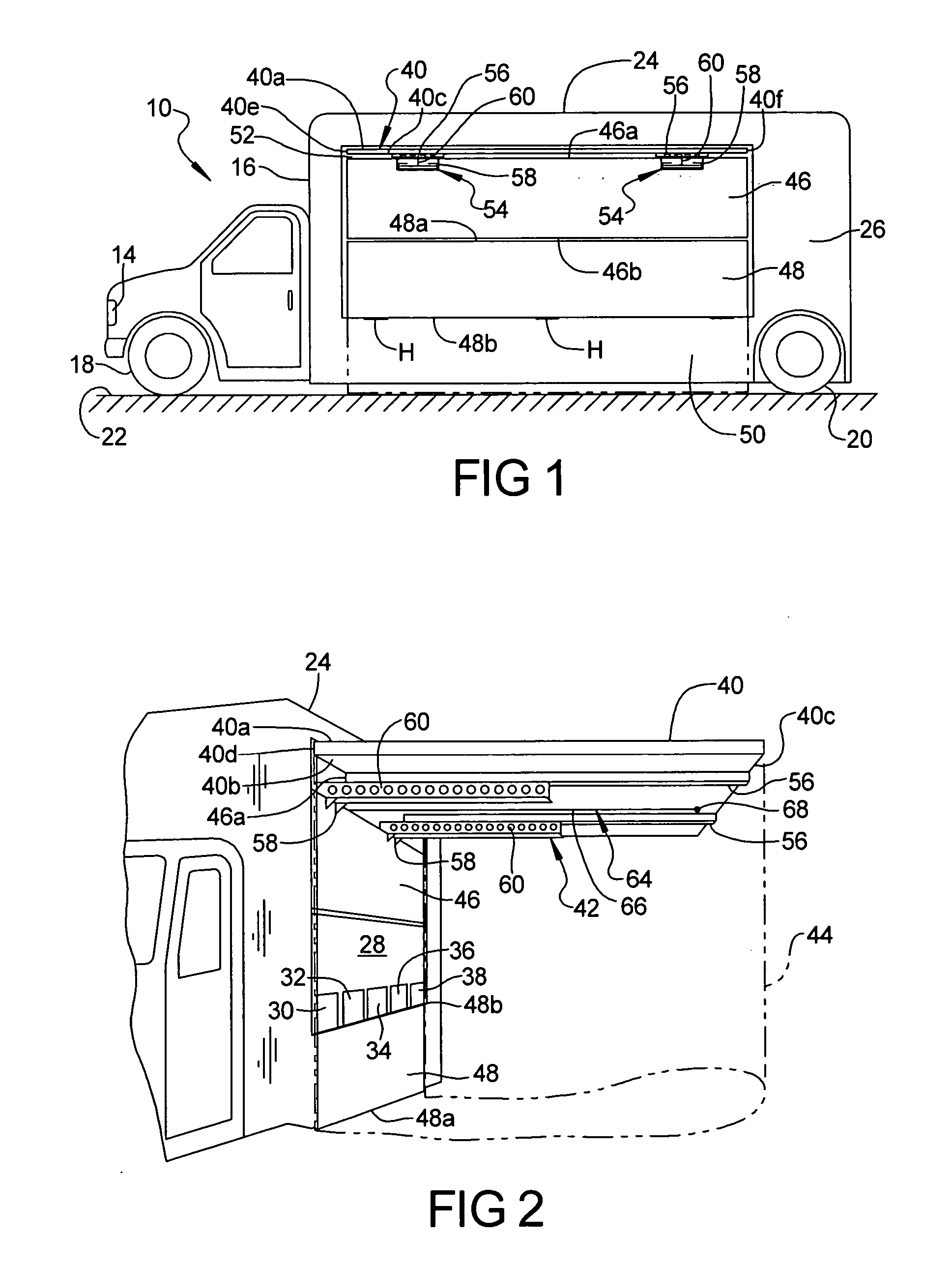
[0012] Advantageously, the enclosure of this invention when used as a deployable paint booth enables a drop cloth of the enclosure to be rapidly configured in enclosing relation about irregular or difficult surfaces to be painted, as desired, or enables the booth to be oriented about and relative to an object to be painted, as desired, or enables a vehicle or like object to be painted to be oriented relative to the roof and drop cloth of the truck booth, as desired.
[0016] a drop cloth which enables the enshrouding of said three sides when the slide roof is extended.
[0023] According to yet another aspect of this embodiment, the paint booth includes vacuum means for lowering the pressure in the enclosure formed by the slide roof, the drop cloth, and the entrance / exit sidewall of the truck, wherein to withdraw paint fumes and chemicals from the enclosure during a paint operation.
[0051] means for removably securing the enclosure wall to the roof section and to hang vertically therefrom when said roof section is in said second position.

Problems solved by technology

Although most of the paint being sprayed adheres to the surface, a certain percentage does not and results in “overspray”.
There are many situations wherein objects need to be painted in situ, either because the objects are permanently or semi-permanently fixed in place or are too heavy or cumbersome for transportation.
This involves considerable time and expense and often does not provide an optimum covering around the object to be painted or may fail to provide proper ventilation in the painting area.
In other situations, it is often desirable to paint an automobile undergoing restoration while the automobile is not fully mechanically restored, and, thus, is not movable.

Method used


Image

  • Portable paint booth
  • Portable paint booth
  • Portable paint booth

Examples


Embodiment Construction

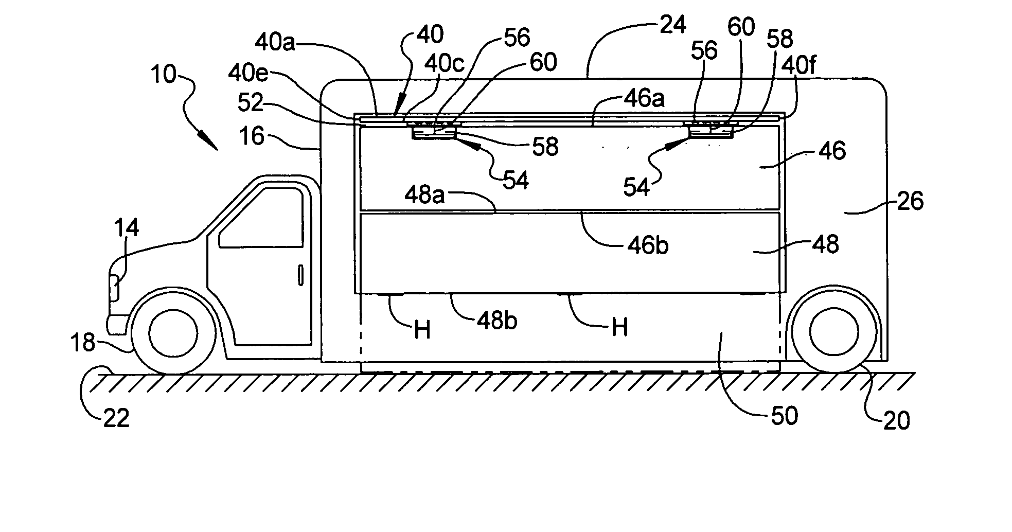
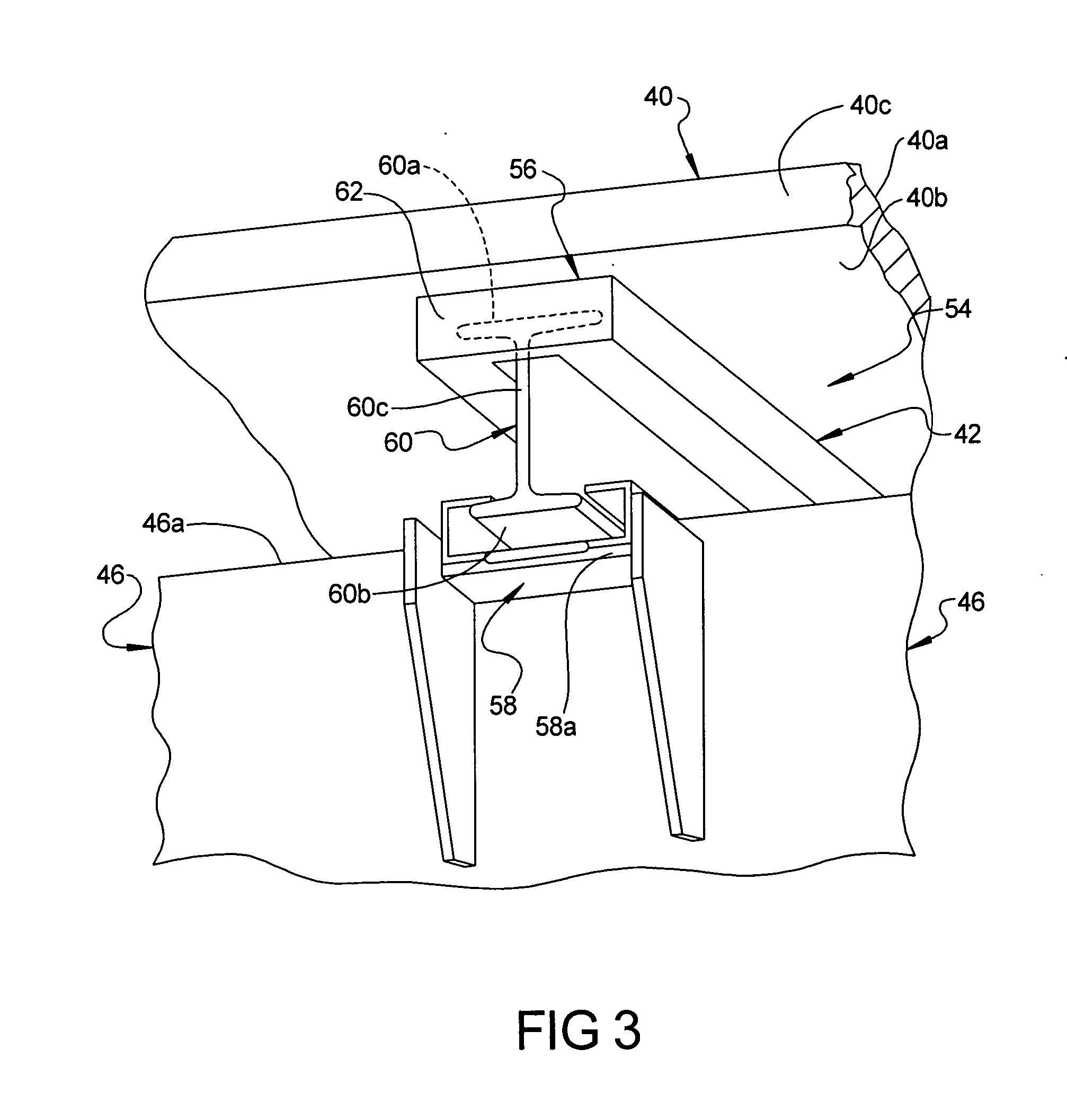
[0078] With reference to FIGS. 1-3 there is shown a truck or like mobile vehicle 10 configured to transport or otherwise carry a booth system for creating a temporary in situ enclosure at a remote location. The discussion herein is with particular reference to a portable, temporary, deployable, in situ paint booth 12, transported by a truck configured for such purpose, although the deployable booth system can be used in other applications.

[0079] Referring to FIG. 1, the truck 10 includes a forward passenger area 14, a rearward transport area 16, and pairs of forward and rearward wheels 18 and 20 for supporting the truck areas 14 and 16 above the ground 22. The rearward transport area 16 is box-like and includes a floor, a ceiling or roof 24, a pair of opposed laterally spaced sidewalls, and a pair of opposed laterally spaced forward and rearward endwalls, the sidewalls and endwalls extending vertically between the floor and ceiling and cooperating to form a box-like truck interior ...


PUM


Abstract

A mobile booth system, carried by a truck or like mobile vehicle, creates a portable, temporary in situ booth or enclosure at a remote location. A pair of side by side slide assemblies are formed by respective nests of C-channels and I-beams, each assembly extending and retracting through an opening in a sidewall of the truck wherein to deploy and retract a roof section outwardly from the truck. The roof section is deployed through a dedicated opening in the sidewall, which opening may be closed by a closure panel but opened by deployment of the roof section. When deployed, an enclosure is formed by attaching a drop cloth to the roof section. The enclosure when used as a paint booth enables rapid deployment of a drop cloth about irregular or difficult surfaces to be painted, as well as to contain overspray and fumes created by the spraying operation.

Description

CROSS-REFERENCE TO RELATED APPLICATIONS [0001] This is a Completion Application of co-pending U.S. Provisional Patent Application Ser. No. 60 / 705,739, filed Aug. 4, 2005, the entire disclosure of which incorporated herein by reference.BACKGROUND OF THE INVENTION [0002] 1. Field of the Invention [0003] This invention is directed to a mobile booth system that is carried by a truck or like mobile vehicle for creating a temporary in situ enclosure at a remote location, and more particularly, to a portable, temporary, in situ paint booth. [0004] 2. Description of Prior Art [0005] Application of paints or chemicals by spraying involves atomizing the paint or chemical using pressurized air, creating a fine mist. This mist is directed towards the surface being painted. Although most of the paint being sprayed adheres to the surface, a certain percentage does not and results in “overspray”. A common way to control overspray and contain fumes is by spraying in a confined booth around the work...

Claims


Application Information

Patent Timeline
IPC IPC(8): B05B15/12
CPCB05B16/40B05B16/80
Inventor ANTAYA, BRUCE
Owner ANTAYA BRUCE C
Learn More