
Medium conveying apparatus, medium feed control method, and image forming apparatus using the control method

a technology of conveying apparatus and control method, applied in the direction of thin material processing, article separation, printing, etc., can solve the problem of recurrent determination of overlap feed

Inactive Publication Date: 2007-03-01
OKI DATA CORP
View PDF4 Cites 6 Cited by
  • Summary
  • Abstract
  • Description
  • Claims
  • Application Information

AI Technical Summary

Benefits of technology

[0006] It is an object of the invention to provide a medium conveying apparatus and a medium feed control method for preventing an overlap-feed of recording media and an image forming apparatus using the control method.

Problems solved by technology

However, even if they were temporarily returned into the paper feeding apparatus and supplied to the conveying path again, it is often repetitively determined that the overlap-feed has occurred.
It is, therefore, a problem to be solved that in the conventional medium conveying apparatus, if the thickness detected by the medium thickness sensor exceeds the predetermined thickness, it is determined that the overlap-feed has occurred, so that the recording media are temporarily returned into the paper feeding apparatus and supplied to the conveying path again, and in such a case, the recovery operation is often repeated many times and the conveyance of the recording media is stopped (a jam error is displayed) eventually.

Method used


Image

  • Medium conveying apparatus, medium feed control method, and image forming apparatus using the control method
  • Medium conveying apparatus, medium feed control method, and image forming apparatus using the control method
  • Medium conveying apparatus, medium feed control method, and image forming apparatus using the control method

Examples


embodiment 1

[0044] First, a construction of an image forming apparatus to which the invention is applied and an outline of its operation will be described.

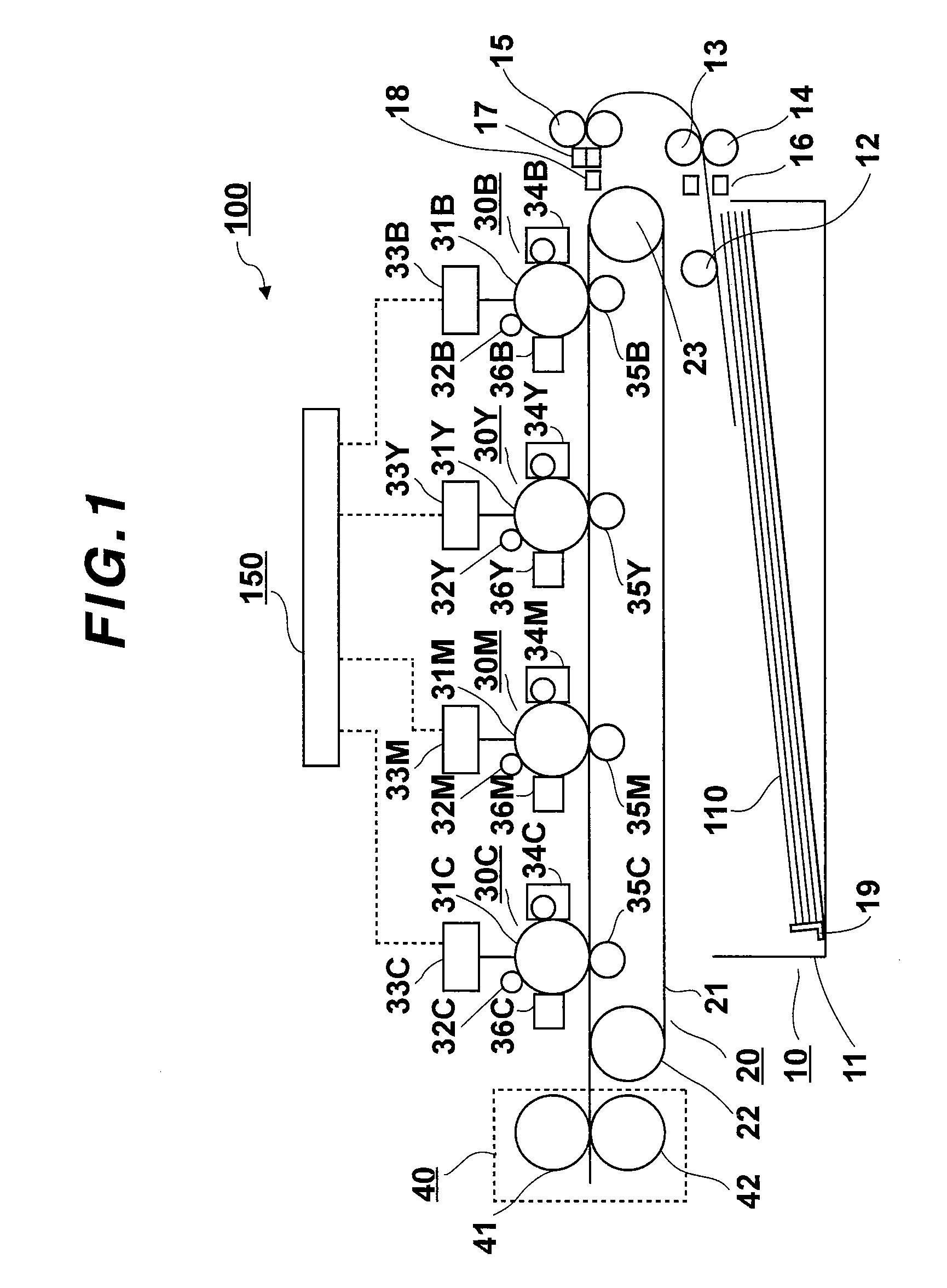
[0045]FIG. 1 is a schematic side elevational view of the image forming apparatus to which the invention is applied.

[0046] As shown in the diagram, an image forming apparatus 100 to which the invention is applied has the following component elements which are arranged in a casing of a main body of the apparatus: a paper feeding unit 10; a conveying belt mechanism unit 20; an image forming unit 30C of cyan (C); an image forming unit 30M of magenta (M); an image forming unit 30Y of yellow (Y); an image forming unit 30B of black (B); a fixing unit 40; and a control unit 150.

[0047] In the paper feeding unit 10, a bundle of sheets of recording paper 110 which are laminated in a paper feed cassette 11 are picked up one by one from a recording paper guide 19 by a pickup roller 12 and fed to a looseness detecting sensor 16. When the looseness detec...

embodiment 2

[0093] Although the upward looseness has been formed in the overlap-feed media by the looseness forming procedure in the embodiment 1, a process to further form a downward looseness is added in the embodiment 2. To accomplish such an object, a medium feed control method of the embodiment 2 is constructed as follows.

[0094]FIG. 8 is a block diagram showing a construction of medium feed control in the embodiment 2.

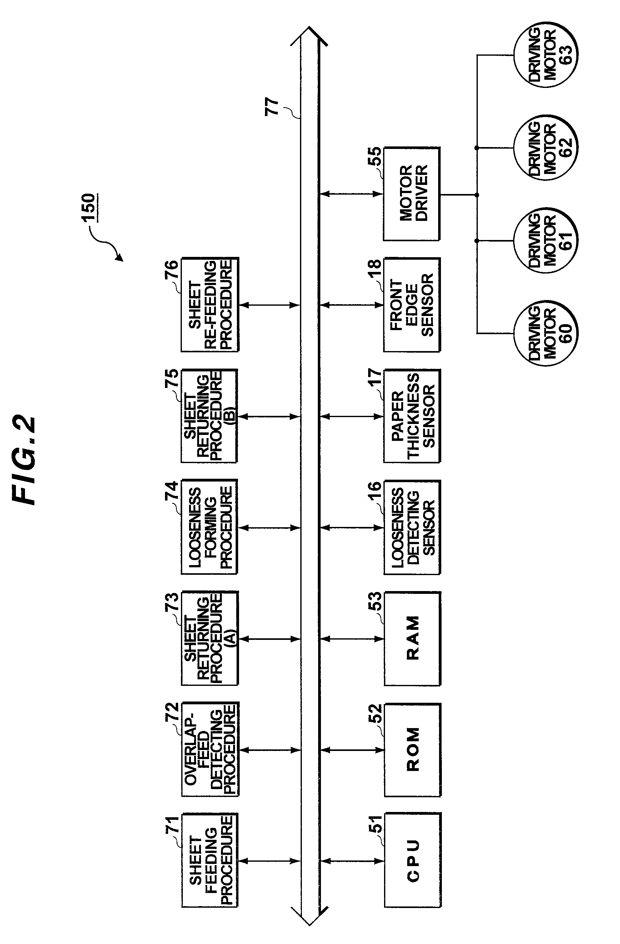
[0095] As shown in the diagram, a control unit 250 to execute the medium feed control in the image forming apparatus of the embodiment has: a CPU 84; a ROM 85; the RAM 53; a looseness detecting sensor 83; the paper thickness sensor 17; the front edge sensor 18; the motor driver 55; the sheet feeding procedure 71; the overlap-feed detecting procedure 72; the sheet returning procedure (A) 73; a looseness forming procedure (A) 81; a looseness forming procedure (B) 82; the sheet returning procedure (B) 75; the sheet re-feeding procedure 76; and the common bus 77. Only portions ...


PUM


Abstract

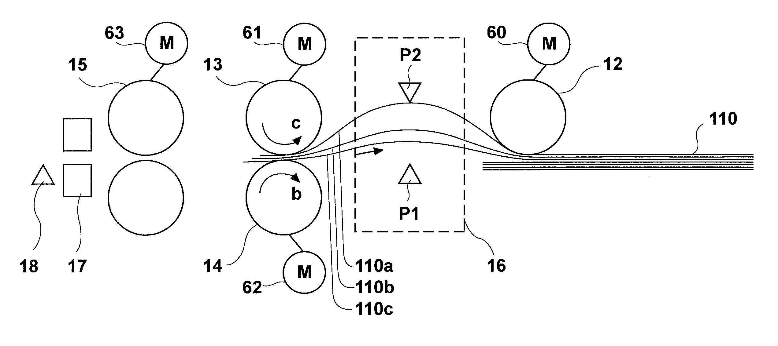
A sheet feeding procedure supplies recording media from a medium enclosing portion to a medium conveying path. An overlap-feed detecting procedure monitors a thickness of recording media supplied to the medium conveying path, thereby detecting the overlap-feed media. Sheet returning procedures (A) and (B) return the overlap-feed media into the medium enclosing portion when the overlap-feed media are detected. A looseness forming procedure applies rotational forces of different rotation speeds to upper and lower surfaces of the overlap-feed media during the medium returning procedure, thereby forming a looseness in the overlap-feed media. A medium re-feeding procedure supplies again the returned recording media to the medium conveying path from the medium enclosing portion. In the medium feed control, the overlap-feed can be further certainly recovered.

Description

BACKGROUND OF THE INVENTION [0001] 1. Field of the Invention [0002] The invention relates to a medium conveying apparatus, a medium feed control method, and an image forming apparatus using the control method and, more particularly, to a control method of preventing an overlap-feed of recording media and an image forming apparatus using the control method. [0003] 2. Related Background Art [0004] In recent years, various image forming apparatuses have been developed and there are many kinds of recording media which are used in the image forming apparatuses. Therefore, development of a technique of a sheet feeding mechanism for feeding the optimum recording medium is also a significant subject (for example, refer to JP-A-2002-46882). Particularly, in an image forming apparatus for forming a full-color image, since image quality is improved if the image is recorded onto thick paper, it is demanded to accurately convey the recording media of various thicknesses. According to the related...

Claims


Application Information

Patent Timeline
Patent Type & Authority Applications(United States)
IPC IPC(8): B41J13/00
CPCB41J11/006B41J13/0045B41J13/0018B41J11/0095
Inventor SONODA, MASAHIRO
Owner OKI DATA CORP
Learn More