Shift range switching apparatus
a technology of shifting range and switching apparatus, which is applied in the direction of electric controllers, hoisting equipment, instruments, etc., can solve the problems of deteriorating the accuracy of control of the shifting range switching mechanism
- Summary
- Abstract
- Description
- Claims
- Application Information
AI Technical Summary
Benefits of technology
Problems solved by technology
Method used
Image

Examples
first embodiment
(Description of Shift Range Changing Device)
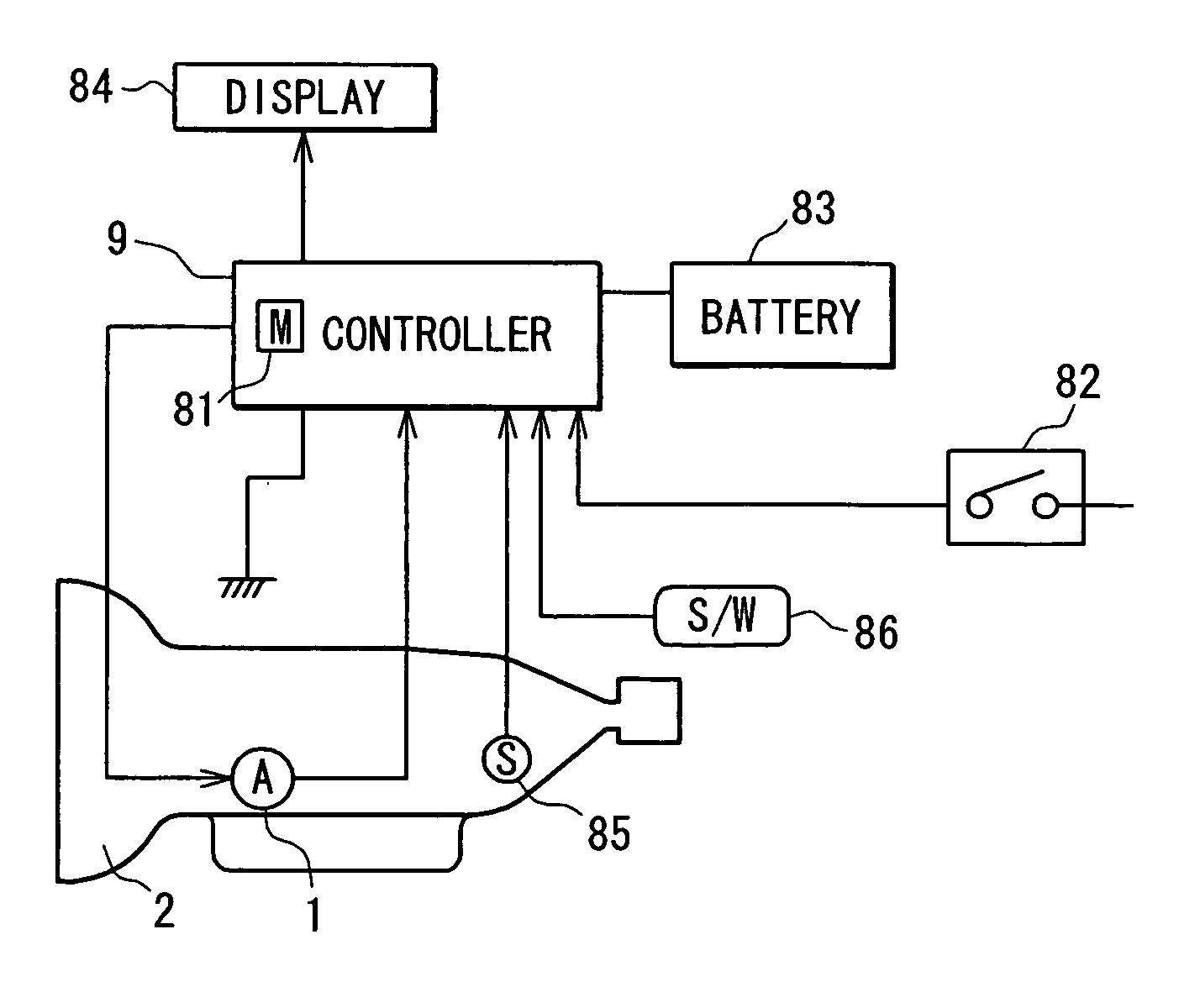
[0019] Referring to FIGS. 2-4, a shift range switching device switches the actual shift range position of a shift range switching mechanism 3 (including a parking mechanism 4 shown in FIG. 4) by use of an electrically operated actuator 1.
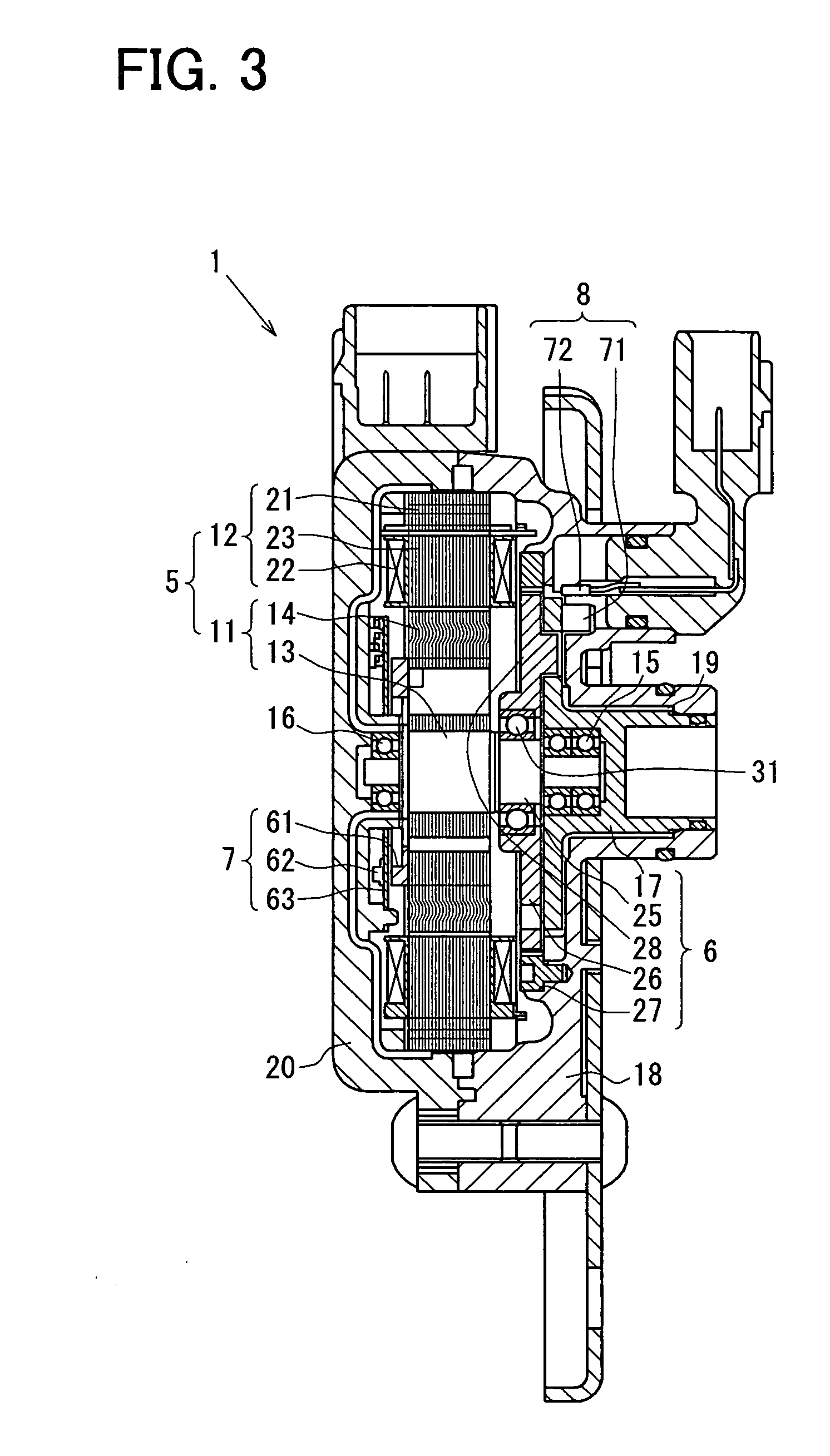
[0020] The electrically operated actuator 1 is a servo mechanism for driving the shift-range-switching mechanism 3 and includes a synchronous electric motor 5, a reduction gear 6 for reducing the rotational output of this electric motor 5 to drive the shift-range-switching mechanism 3, a rotor angle detecting means 7 for detecting the rotational angle of the electric motor 5, and output angle detecting means 8 for detecting the output angle of the reduction gear 6, which corresponds to the actual shift range position. An electric motor controlling means 9 controls rotation direction, rotation speed, rotation amount, and rotation angle of the electric motor 5 through the reduction gear 6.
[0021] In FIG. ...
second embodiment
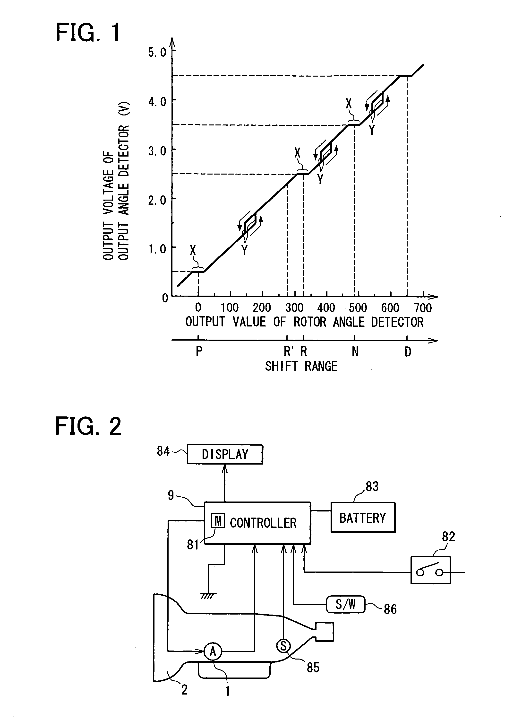
[0087] According to a second embodiment, the recognized position correcting means corrects the output shaft angle which the motor controller 9 recognizes so as to correspond to the actual shift range position based on the small range X in which the variation in output shaft angle is relatively small with respect to the variation in rotor angle. Thereby, even if a deviation is generated between the output shaft angle and the actual shift range position due to the mechanical backlash of the actuator 1 and the shift range switching mechanism 3, the output shaft angle can be corrected so as to correspond to the actual shift range position. The detection accuracy of the actual shift range position based on the output shaft angle is enhanced. That is, an analog output characteristic of the output shaft angle detecting means 8 is changed due to a variation in magnetic force of the magnet 71, the output shaft angle is correctly detected.
third embodiment
[0088] Referring to FIGS. 6 and 7, a third embodiment is described hereinafter. The detent mechanism 40 includes the detent plate 46 and an engaging means which engages with the detent grooves 46a. The engaging means includes the engaging roller 47a, a piston 47b, and a coil spring 47c. The piston 47b reciprocates in a cylinder 41a which is formed in a housing of a hydraulic controller 41. The coil spring 47c biases the piston 47b toward a rotation center of the detent plate 46, so that the engaging roller 47a is biased to the bottom of the detent groove 46a. The detent mechanism 40 has the same function as the first embodiment.
(Modification)
[0089] In the first embodiment, the backlash amount is obtained in the small range X in which a variation in rotor angle is relatively large with respect to the variation in output shaft angle.
[0090] According to a modification, as shown in FIG. 8, the mechanical backlash can be obtained based on a large range X in which the rotor angle chan...
PUM
 Abstract
Description
Claims
Application Information
 - R&D
- Intellectual Property
- Life Sciences
- Materials
- Tech Scout
- Unparalleled Data Quality
- Higher Quality Content
- 60% Fewer Hallucinations
Browse by: Latest US Patents, China's latest patents, Technical Efficacy Thesaurus, Application Domain, Technology Topic, Popular Technical Reports.
© 2025 PatSnap. All rights reserved.Legal|Privacy policy|Modern Slavery Act Transparency Statement|Sitemap|About US| Contact US: help@patsnap.com