Eureka AIR delivers breakthrough ideas for toughest innovation challenges, trusted by R&D personnel around the world.

Thermostat including set point number line

a technology of thermostat and number line, which is applied in the field of digital thermostats, can solve the problems of not providing any indication to the user of the relationship, and the type of digital numeric display does not provide the same visual cues that were availabl

Inactive Publication Date: 2007-03-01
RANCO OF DELAWARE
View PDF31 Cites 125 Cited by
  • Summary
  • Abstract
  • Description
  • Claims
  • Application Information

AI Technical Summary

Benefits of technology

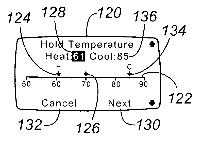
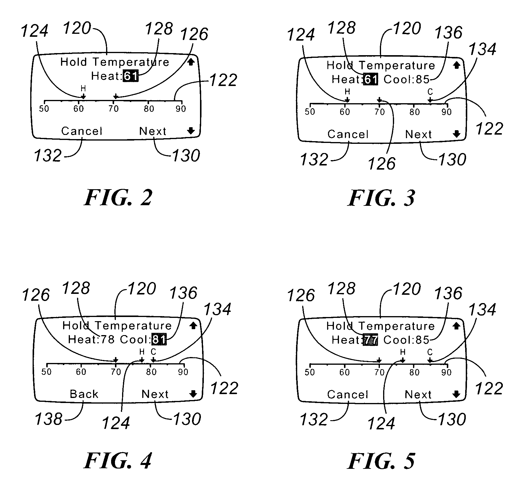
"The present invention provides a new and improved digital thermostat with a temperature programming display system that allows the user to visually see the heating and cooling set points and the ambient temperature. The display system includes a user display screen with the ability to display graphical elements, such as digital icons and markers, along the temperature number line. The user can adjust the heating and cooling set points and the corresponding digital icon will move along the temperature number line to show the current status of the equipment. The display system also shows the minimum distance between the two temperature set point markers, which can be adjusted by the user. When one set point is moved to within the dead band temperature of the other, the other set point cannot be moved further unless the user moves the other set point. Overall, the invention provides a more intuitive and user-friendly programming experience for the digital thermostat."

Problems solved by technology

This, however, does not provide any indication to the user of the relationship among the adjusted set point, the other set point, or the ambient temperature itself.
As a result, the user may inadvertently attempt to program a set point for one type of HVAC equipment that interferes with the set point for the other HVAC equipment.
Similarly, the user may attempt to adjust one of the set points to either increase or decrease the ambient temperature within the dwelling without success.
That is, this type of digital numeric display does not provide the same visual cues that were available on the older mechanical thermostats.
As such, the user may still inadvertently attempt to set the heating and / or cooling set point at a temperature that would interfere with the proper operation of the heating and / or cooling equipment.
As a further example, if the cooling temperature set point is set to 72° and the user is cold, the user may inadvertently attempt to set the heating set point to 74°, not realizing that this would theoretically result in operation of both the heating and cooling equipment at the same time.

Method used


Image

  • Thermostat including set point number line
  • Thermostat including set point number line
  • Thermostat including set point number line

Examples


Embodiment Construction

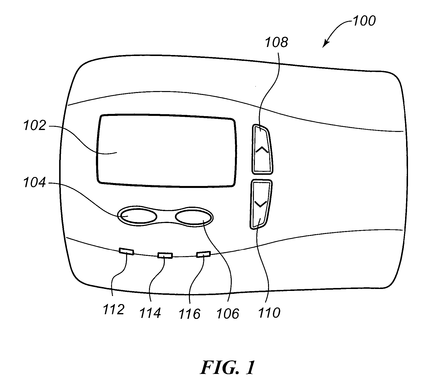
[0026] An embodiment of a thermostat constructed in accordance with the teachings of the present invention that incorporates the temperature programming display system of the present invention is illustrated in FIG. 1. As with many thermostats, an internal temperature sensor that is monitored by the internal processor is included within the thermostat 100. As may be seen from this FIG. 1, this embodiment of the thermostat 100 includes a user display 102 on which is displayed programmatic, system, and ambient information regarding the operation of the HVAC system. This user display 102 may take various forms as are well-known in the art, and in a preferred embodiment is a dot matrix LCD display. With such a display 102, the consumer may activate various programmatic and control functions via a pair of soft keys 104, 106. The functionality executed by these soft keys 104, 106 varies dependent upon the programmatic state in which the thermostat 100 is at the time one of the soft keys 1...


PUM


Abstract

A thermostat temperature programming display system for a digital thermostat that provides a graphical illustration of the relationship between the heating, cooling, and ambient temperatures is provided. This display system illustrates this relationship as digital markers along a linear temperature set point line on the display. As a set point is varied, the digital marker moves along the set point line. The heating and cooling set point markers are bounded by one another in a variable relationship based on a user defined dead band temperature during an automatic change over mode of operation. Only an appropriate marker is illustrated on the set point line based on the operating mode of the thermostat.

Description

FIELD OF THE INVENTION [0001] The present invention relates generally to digital thermostats, and more particularly to the display of temperature set point programming information on a digital thermostat. BACKGROUND OF THE INVENTION [0002] Occupants of dwellings and commercial structures have long benefited from the inclusion of a heating, ventilating, and air conditioning (HVAC) system that regulates the temperature and humidity within the dwelling or structure. Traditionally, the thermostat that controlled this temperature regulating equipment was a fairly simple electromechanical device that was simply wired to a heating device and / or to a cooling device. Once installed, the user need only move a pair of slider switches, one for heat and one for cool, to set the heating and cooling temperatures desired. [0003] These two slider switches would typically move two indicators along a linear, mechanical temperature scale on the thermostat. When adjusting the temperature on such a therm...

Claims


Application Information

Patent Timeline
Patent Type & Authority Applications(United States)
IPC IPC(8): G05D23/00F23N5/20
CPCF23N5/022G05D23/1902F23N2041/02F23N2025/12F23N2225/12F23N2241/02F25B49/00G05B13/02G05B23/00
Inventor GRAY, TONYCHAPMAN, JOHN GILMAN JR.
Owner RANCO OF DELAWARE
Why Eureka
Eureka Blog
Learn More