
Self-supported riser system and method of installing same

a self-supporting, riser technology, applied in the direction of passenger handling apparatus, transportation and packaging, borehole/well accessories, etc., can solve the problems of high operational cost, construction and assembly of the riser, and the practicability of lowering, so as to reduce the maneuvering steps and save the time of the rig

Inactive Publication Date: 2007-03-01
PETROLEO BRASILEIRO SA (PETROBRAS)
View PDF13 Cites 87 Cited by
  • Summary
  • Abstract
  • Description
  • Claims
  • Application Information

AI Technical Summary

Benefits of technology

[0019] iii) The riser is used to lower and install the WCT, a procedure which saves rig time and reduces maneuvering steps.
[0023] The present invention also provides a self-supported riser system for use in an Anticipated Production System or in a Long Duration Test in which the riser is used to lower and install the WCT, thereby saving rig time and reducing the maneuvering steps.

Problems solved by technology

This production system is characterized by its high operational cost, in as much as it utilizes a vessel of low availability in the world service market.
Only anchored vessels may be used in this configuration since there is no unwinding system or solution which provides the function of a swivel.
The arrangement described in U.S. Pat. No. 4,646,840 provides little practicability for lowering a WCT utilizing a production riser.
In addition, a riser containing several ducts (conveyance pipes) and an insulation system, constructed and assembled at a dry enclosed location (on land) can prove troublesome and quite limited once it is relocated and installed in place, since the procedure of soldering joints cannot be adapted for variable water depths (WD), such procedure being limited to specific and fixed water depths (WD).

Method used


Image

  • Self-supported riser system and method of installing same
  • Self-supported riser system and method of installing same
  • Self-supported riser system and method of installing same

Examples


first embodiment

[0101] In accordance with the first embodiment, generally shown in FIGS. 6 to 18, the installation method of the riser system (100) comprises the following steps: [0102] a) hoisting the buoy assembly (60), by means of a crane (G), (FIG. 6), from a dock and placing it in a transportation raft (802). As an alternative, the buoy assembly may be placed on the raft by sliding it on the dock surface. Following the placement on the raft, sea fastening the buoy assembly to avoid dislocation of the buoy assembly on the raft during the oceanic transport; [0103] b) transporting the raft (802) and the buoy assembly (60), with the aid of a tug (803), (FIG. 7), to the location at which the riser system (100) is to be installed; [0104] c) in the proximity of a semi-submersible platform (804) for lowering the riser (50), (FIG. 8), connecting the buoy assembly (60): i) utilizing a cable (805) to a semi-submersible platform (804) and ii) utilizing a cable (806) connecting the buoy assembly to the tug...

second embodiment

[0119] According to this second embodiment, shown on FIGS. 19 to 21, the installation method of the riser system (100) of the following invention includes the following steps: [0120] a) mounting the WCT (20), the BOP preventor (30) and the connection tool (40) on a temporary support unit (901), located in the moon pool region (902) of the installation platform (804). Connecting the riser (50), formed of riser sections, to the connection tool (40), (FIG. 19A) and detail of joint (810) (FIG. 19B); [0121] b) connecting and lowering the sections (810), whose conjoint forms the riser (50), until the required length for the installation of the first buoys (60) is reached; maneuvering the buoy in the moon pool region (902) of the installation platform in order to enclose the riser sections (810) in the center of the buoy through use of the opening (903), so that the buoy (60) is attached to the riser sections (810), (FIG. 20A and detail in FIGS. 20B and 20C); [0122] c) connecting new riser...


PUM


Abstract

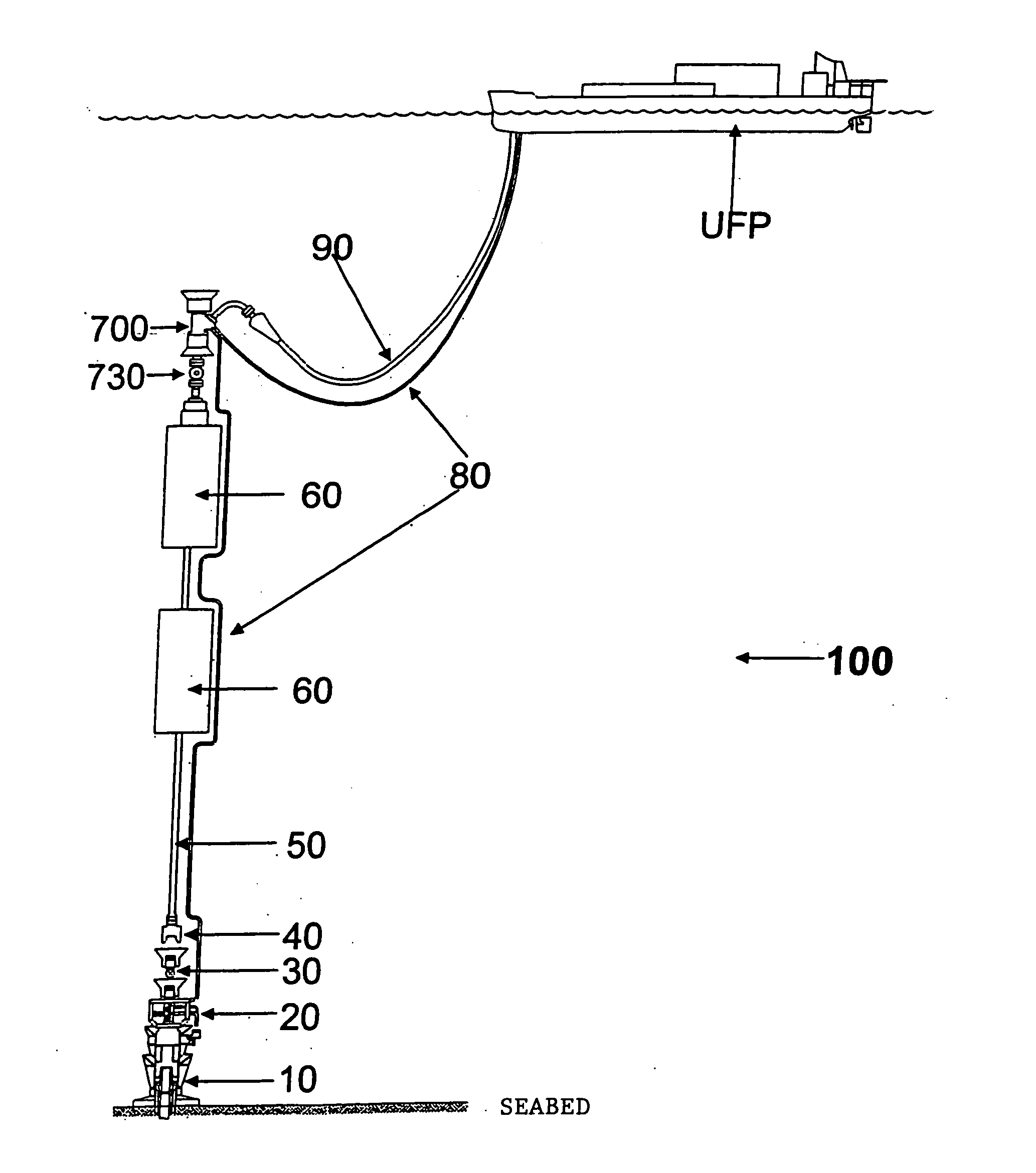
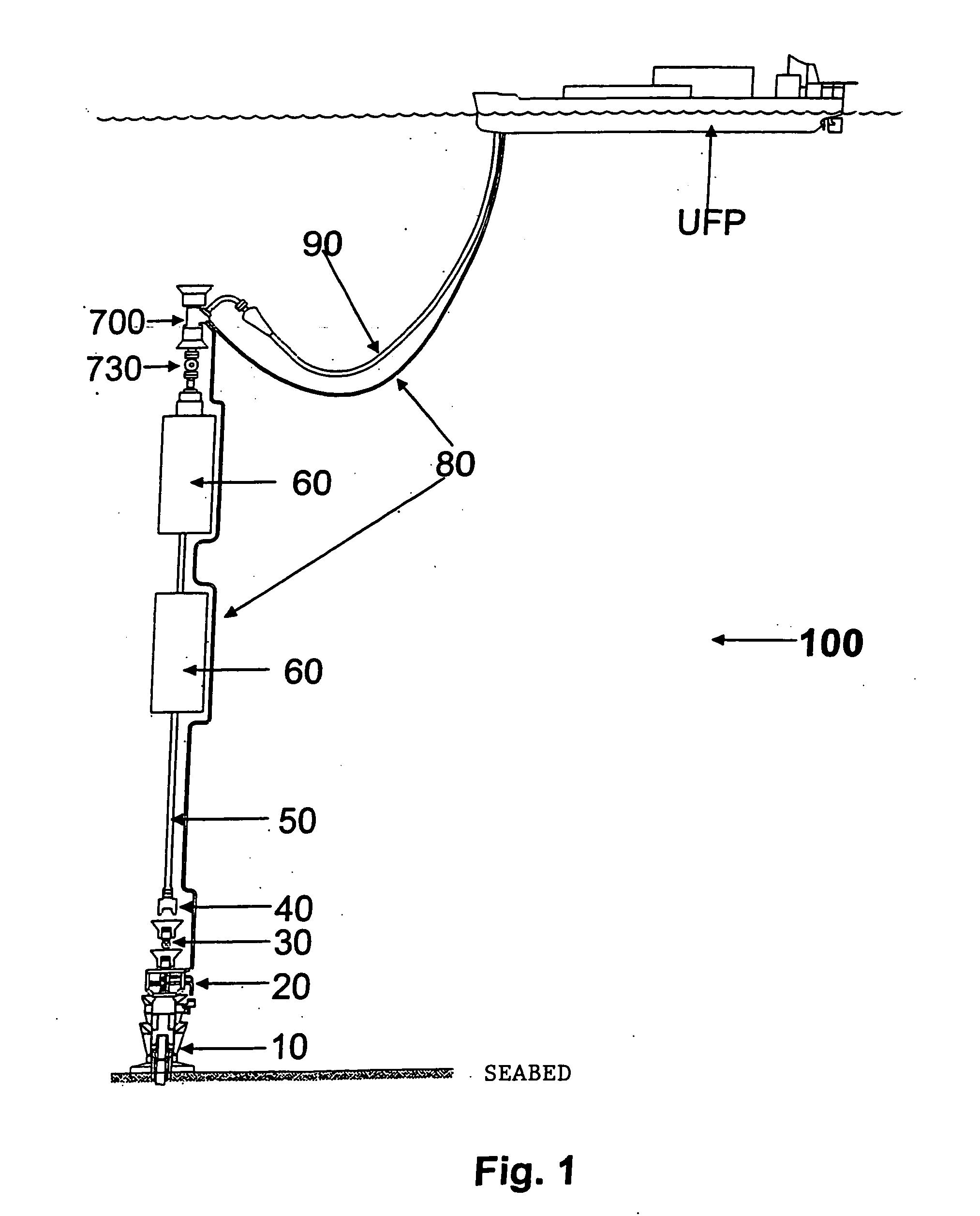
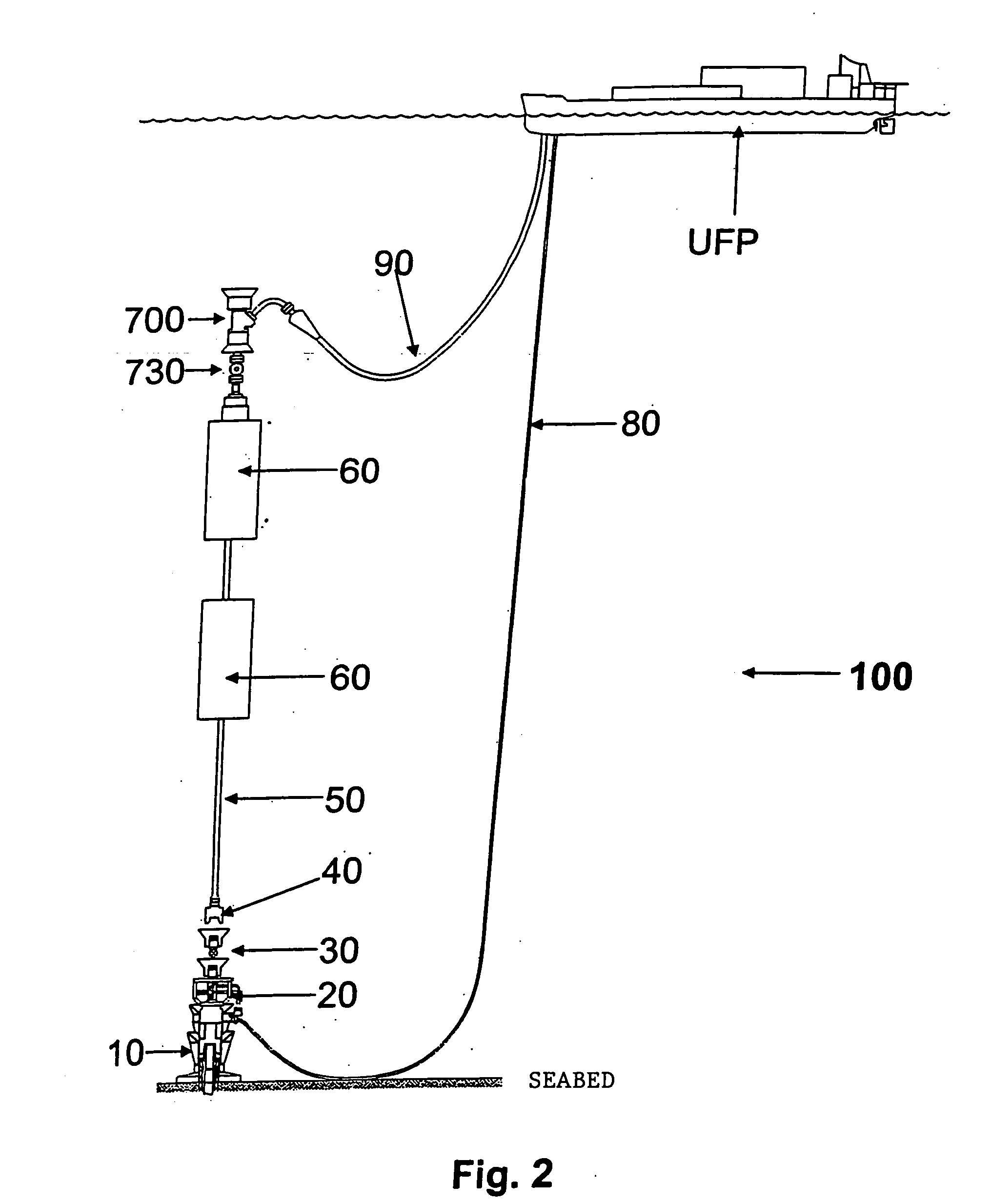
A self-supported riser system (100) for an Anticipated Production System (ASP) Test or a Long Duration Production (LDP) Test in a subsea petroleum production system, utilizing an ANM coupled to a wellhead and Floating Production Unit (FPU) is disclosed. The system includes a wellhead at the seabed, connected to an ANM (20) provided with a preventor (BOP of workover) (30). The preventor (30) is connected to a production riser (50) through a connection tool (40). The riser (50), mounted internally within a buoy assembly (60), is maintained under traction with the aid of a buoy assembly. The upper end of the riser (50) is provided with a Subsea Intervention Terminal (700), the Terminal being interlinked to the FPU by a flexible jumper (90) to carry the oil produced to the FPU. Two methods for installing the self-supported riser system (100) are also disclosed.

Description

FIELD OF THE INVENTION [0001] The present invention relates to a system of a self-supported riser, and more specifically, to a system where a riser is coupled at its lower end to equipment of the type known as a WCT—Wet Christmas Tree or a manifold, the riser being supported in an straight position (vertically) by a group of buoys located proximate the upper end of the riser, which also comprises a Submarine Intervention Unit connected to a Floating Production Unit (FPU) through a flexible jumper. The invention is to be applied in Anticipated Production Systems (APS), in Long Duration Tests (LDT) for better evaluation of reservoirs and may also be used as a completion riser. The present invention further relates to a method for installing of said self-supported riser system. BACKGROUND OF THE INVENTION [0002] One of the production systems presently utilized by the Applicant employs a production system which utilizes a dynamically positionable offshore vessel fitted with a derrick, a...

Claims


Application Information

Patent Timeline
Patent Type & Authority Applications(United States)
IPC IPC(8): E21B17/01
CPCB63B27/24E21B17/012E21B43/0107
Inventor ROVERI, FRANCISCO EDWARDSILVA PAULO, CEZAR AUGUSTORODRIGUES, ROBERTOMONSANO, RENATO BRANDAOGIACOMIN PEREIRA, CARLOS ALBERTO
Owner PETROLEO BRASILEIRO SA (PETROBRAS)
Learn More