
Guideway activated magnetic switching of vehicles

a technology of magnetic switching and guideway, applied in the direction of routes, rope railways, transportation and packaging, etc., can solve the problems of maintenance problems, not safe to use switches, and require several seconds to activa

Inactive Publication Date: 2007-03-01
MAGNEMOTION INC
View PDF98 Cites 94 Cited by
  • Summary
  • Abstract
  • Description
  • Claims
  • Application Information

AI Technical Summary

Benefits of technology

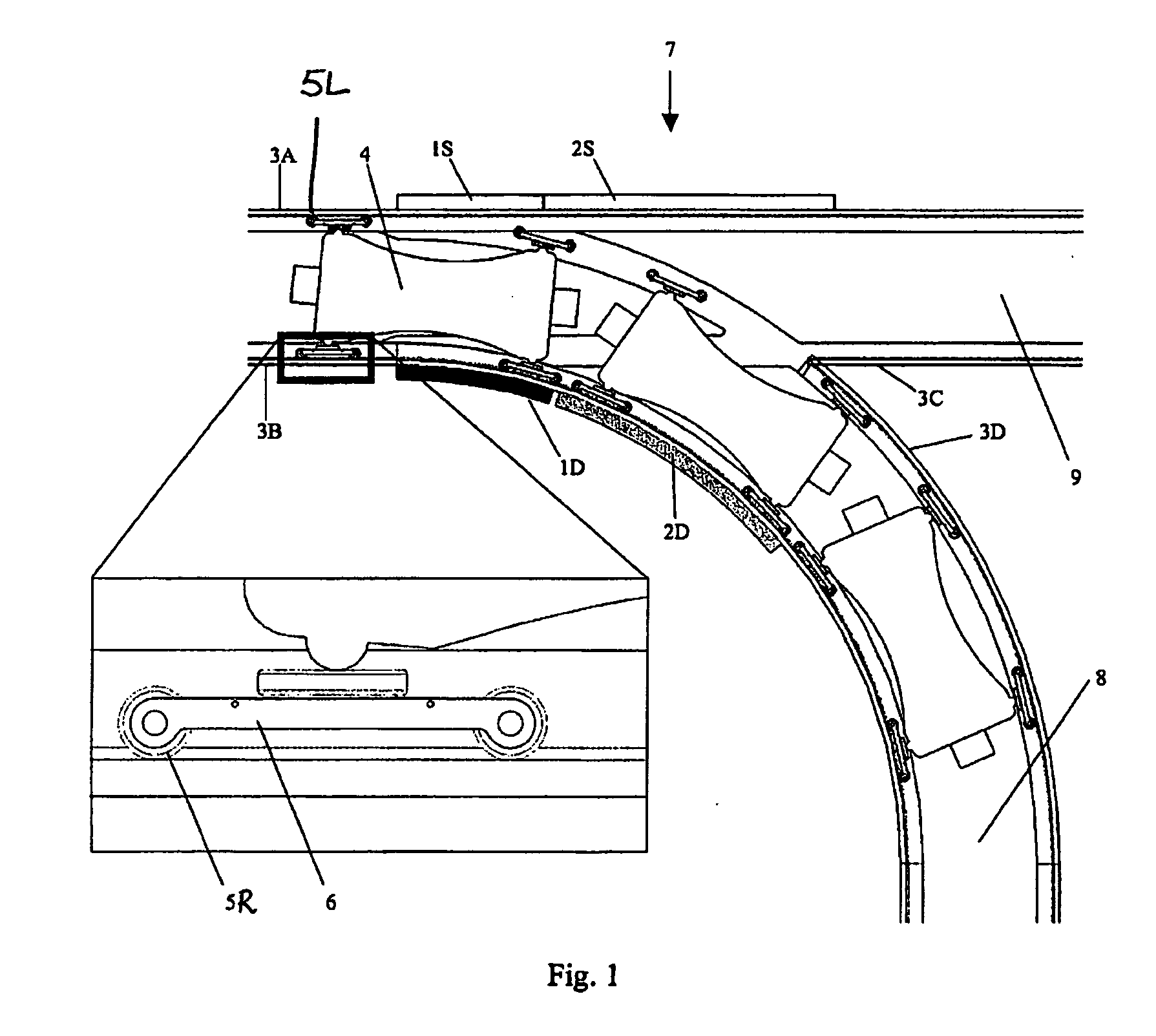
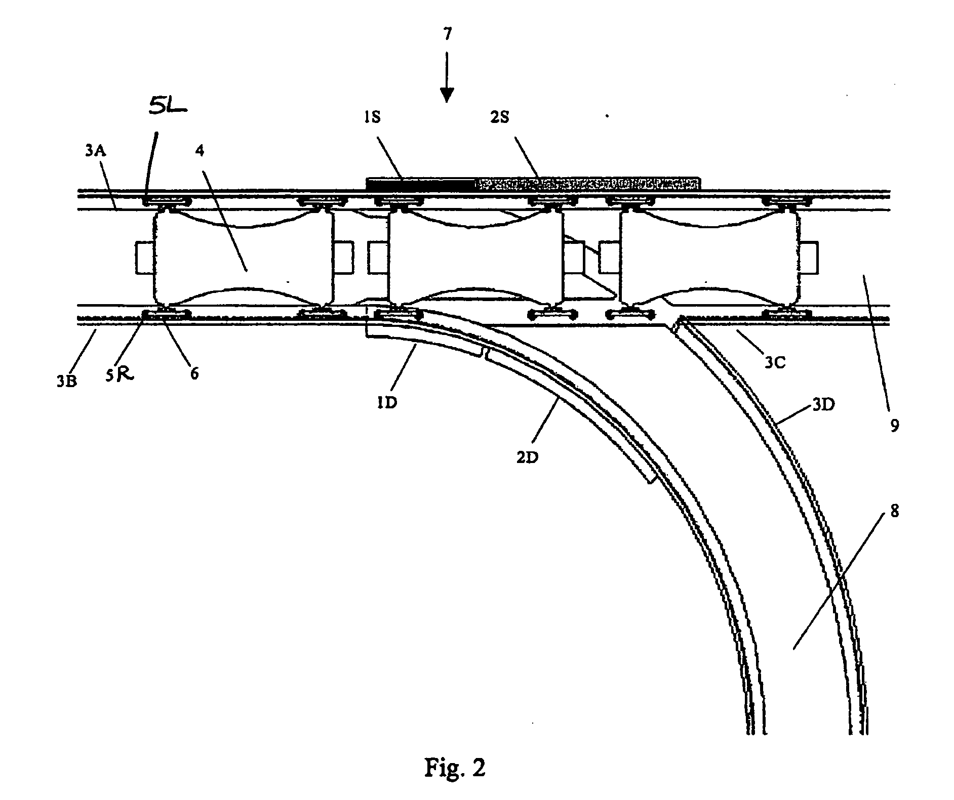
[0014] According to further aspects of the invention the switching is initiated by an electromagnet but once the vehicle moves a short distance the switching is completed by means of one or more permanent magnets located on the guideway. A permanent magnet can keep the vehicle on the desired path until the normal guidance mechanism is effective.
[0015] Methods and apparatus according to the invention are suited for, among other things, guiding vehicles that are propelled by a linear motor. With this propulsion scheme and guideway-based magnetic switching the entire propulsion and control system can be located on the guideway so the vehicle can be passive and there is no need to transmit control signals to a moving vehicle.
[0016] These and other aspects of the invention are evident in the drawings and in the claims that follow.

Problems solved by technology

Conventional trains use switches with mechanically movable rails that require several seconds to actuate and have maintenance problems.
In these cases it is not safe to use switches that require substantial motion of sections of the guideway.
This makes it feasible to operate with short headway, but now there is a reliability problem because the vehicle control must be coordinated via guideway based controllers.
Additionally, the switching mechanisms are mechanical which require maintenance and are vulnerable to failure.
Neither of these methods has achieved wide success and guideway-based mechanical mechanisms continuing to dominate switch design.
These techniques have the advantage of being guideway activated and having no moving parts, but they do not work with most types of suspension in use today.

Method used


Image

  • Guideway activated magnetic switching of vehicles
  • Guideway activated magnetic switching of vehicles
  • Guideway activated magnetic switching of vehicles

Examples


Embodiment Construction

Introduction

[0025] The invention described here is an outgrowth of earlier work by the inventors hereof, described in U.S. Pat. No. 6,101,952, the teachings of which are incorporated herein by reference. The design discussed therein has been successfully used in a commercial application, though improvements of lower complexity and cost are always desirable. As will be appreciated from the discussion below, the magnetic switching disclosed in that patent is modified herein to work with a variety of suspension and guidance schemes, and to use electromagnets on the guideway to create controllable forces on the vehicle to force the vehicle to go in a specified direction at a diverge and to operate safely at a merge

[0026] As shown in the drawings and discussed below, the illustrated embodiment of the invention utilize magnetic forces for diverting or merging vehicles at switch points on a guideway. The switching is achieved by the interaction of a magnetic field produced by one or more...


PUM


Abstract

A system for switching a transport vehicle comprising: a guideway, a vehicle that moves along the guideway, and a magnetic field source that creates a force on the vehicle to affect motion in a desired direction at a switch. Once the vehicle has started motion through the switch the guidance can be continued by use of permanent magnets until the normal guidance system is effective. The switching scheme can work with any suspension scheme, including wheels and maglev, and can work with any lateral guidance scheme, including horizontal guide wheels and magnetic guidance. The system can be used with very closely spaced vehicles, such as with Personal Rapid Transit, material handling, and elevators with multiple cabs in the same shaft.

Description

CROSS REFERENCE TO RELATED APPLICATIONS [0001] This application claims the benefit of the filing date of U.S. Provisional Application No. 60 / 701,777, filed Jul. 22, 2005, the entire contents of which are incorporated herein by reference.BACKGROUND OF THE INVENTION [0002] This invention pertains to vehicular transport and, more particularly, to methods and apparatus for the switching of vehicles on a guideway. [0003] All guideways must have means to choose between alternate directions of travel. Conventional trains use switches with mechanically movable rails that require several seconds to actuate and have maintenance problems. Monorail trains and systems using magnetic or air-cushion suspension typically require motion of large sections of a guideway. Some automated people movers use rubber-tired wheels for suspension and additional vertical-axle wheels for guidance with switching done by moving sections of the guideway. [0004] For some applications, such as personal rapid transit ...

Claims


Application Information

Patent Timeline
IPC IPC(8): B61B13/08
CPCB60L13/003B61B10/001B61B13/04B61B13/08E01B25/12B60L2200/26
Inventor CLARK, TRACY M.MENDENHALL, JESSETHORNTON, RICHARD D.
Owner MAGNEMOTION INC
Learn More