
Film forming method, film forming apparatus, method of manufacturing device, and apparatus for manufacturing device

a technology of film forming and film forming equipment, which is applied in the direction of solid-state devices, printing, optical filters, etc., can solve the problems of unavoidable decrease of throughput and decrease of scanning throughput, so as to prevent the increase of liquid viscosity or the segregation of solid contents within the liquid, prevent the increase of liquid viscosity, and prevent the effect of liquid droplets being discharged stabl

Inactive Publication Date: 2007-02-22
KATEEVA
View PDF8 Cites 7 Cited by
  • Summary
  • Abstract
  • Description
  • Claims
  • Application Information

AI Technical Summary

Benefits of technology

The present invention provides a method and apparatus for film formation that allows for efficient and stable discharge of liquid droplets onto a substrate without decreasing throughput. The method includes a preliminary discharge step of preliminarily discharging liquid droplets from heads and a liquid droplet discharge step of relatively moving the heads and the work to discharge the liquid droplets onto the surface of the work. The preliminary discharge can be carried out while the heads and work are moved relative to each other, and the discharge interval between the preliminary discharge and the liquid droplet discharge onto the work can be minimized to prevent an increase in viscosity or segregation of solid contents. The method can be applied to various devices such as film bodies, coating films, and filter elements.

Problems solved by technology

However, in the conventional art as described above, there are the following problems:
In other words, since the Y-axis table is subjected to a control pattern of acceleration-deceleration-stop-acceleration, there is a problem that the throughput is decreased in the scanning when using the conventional flushing procedure.
Specifically, when discharging a liquid having a tendency to experience clogging or an increase in viscosity, the flushing has to be carried out frequently, and thus if the quality of film is to be maximized, a decrease of throughput is unavoidable.

Method used


Image

  • Film forming method, film forming apparatus, method of manufacturing device, and apparatus for manufacturing device
  • Film forming method, film forming apparatus, method of manufacturing device, and apparatus for manufacturing device
  • Film forming method, film forming apparatus, method of manufacturing device, and apparatus for manufacturing device

Examples


Embodiment Construction

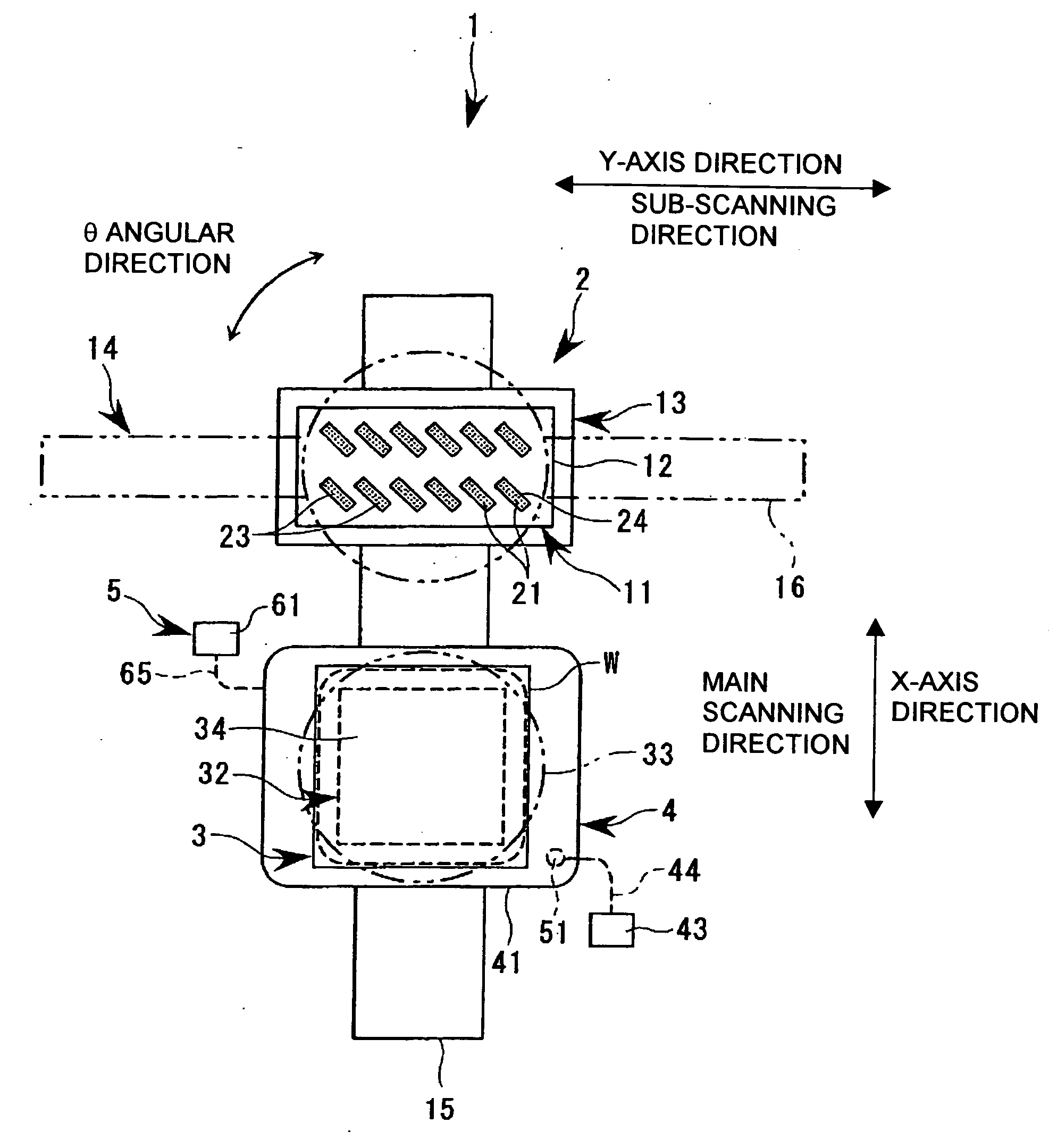
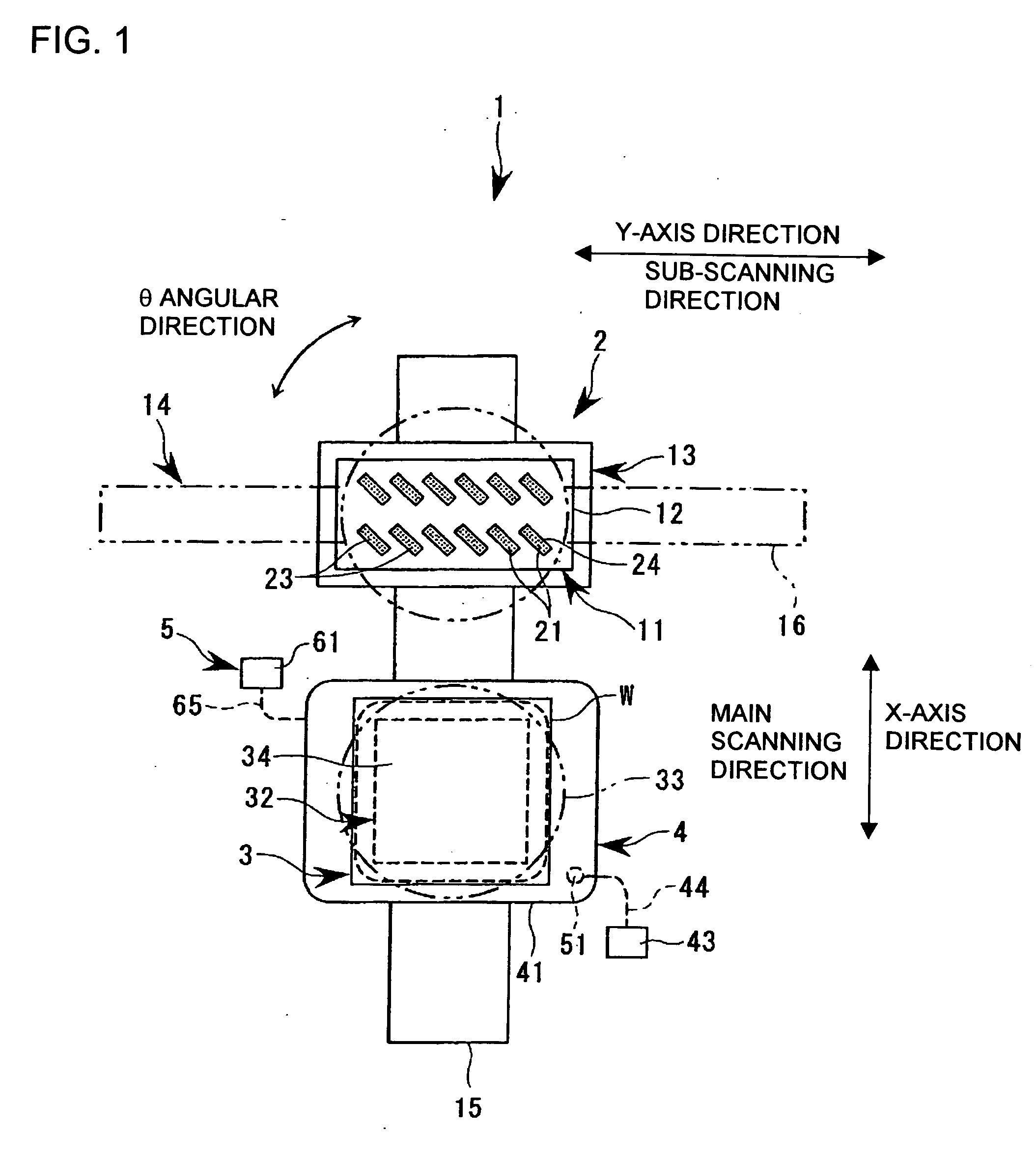
[0035] Now, embodiments of the film forming method, the film forming apparatus, the method of manufacturing a device, and the apparatus for manufacturing a device according to the present invention will be described with reference to FIGS. 1 through 8.

[0036] Here, the film forming apparatus of the present invention is applied to, for example, a liquid droplet discharge apparatus for manufacturing a spectacle lens. In other words, the present invention will be described by way of an example in which a functional liquid is discharged onto the spectacle lens (work) which is a target for the discharge of functional liquid from a liquid droplet discharge head filled with the functional liquid. Specifically, the spectacle lens could be coated with a film body, such as a UV cut agent or an anti-fogger, and thus the work is coated (hard-coated) with a film made from a functional material.

[0037]FIG. 1 is a schematic view illustrating a basic construction of a liquid droplet discharge appar...


PUM

PropertyMeasurementUnit
viscosityaaaaaaaaaa
areaaaaaaaaaaa
speedaaaaaaaaaa

Abstract

The invention provides a film forming method that improves throughput in a preliminary discharge. The film forming method according to the present invention can include a preliminary discharge step of preliminarily discharging liquid droplets from a head and a liquid droplet discharge step of relatively moving the head and the work to discharge the liquid droplets onto the surface of the work from the head. The preliminary discharge of the liquid droplets is carried out while the head and the work are moved relative to each other.

Description

BACKGROUND OF THE INVENTION [0001] 1. Field of Invention [0002] The present invention relates to a film forming method, a film forming apparatus, a method of manufacturing a device, and an apparatus for manufacturing a device, in which a film body made from functional material is formed on the surface of a work using liquid droplet discharge heads. [0003] 2. Description of Related Art [0004] With the development of electronic apparatuses, such as computers or portable information appliances, liquid crystal display devices, specifically, color liquid crystal display devices (LCD) have been more widely used. A liquid crystal display device of this type uses color filters for coloring display images. In a color filter having a substrate as a work, a film may be formed by depositing liquid ink droplets of R (red), G (green), and B (blue) as in a predetermined pattern on the substrate. The method for depositing the inks onto the substrate may include a liquid droplet discharge method, su...

Claims


Application Information

Patent Timeline
Patent Type & Authority Applications(United States)
IPC IPC(8): B05D5/06B05D5/00B05D7/00B05D5/12B05C5/00B05C5/02G02C7/02B05C11/10B05D1/26B41J2/01G02B1/10G02B5/20G02F1/1335H01L51/50H05B33/10
CPCB05C5/02B05C11/1039G02F1/133516H01L51/0005H10K71/135B41J2/01
Inventor KOYAMA, MINORU
Owner KATEEVA
Learn More