
Emptying device

Active Publication Date: 2007-02-22
SCHEUGENPFLUG
View PDF15 Cites 15 Cited by
  • Summary
  • Abstract
  • Description
  • Claims
  • Application Information

AI Technical Summary

Benefits of technology

[0021] After emptying the container completely, the drum follower plate, whose intermediary space is at least partially filled with paste, is disposed of, together with the container, therefore the follower plate is made from plastic in an economical manner.
[0028] Furthermore it is advantageous when the elevation differential between the upper plate and the grid plate is in increased towards the vacuum connector or towards the overflow, in order to avoid sealing between upper plate and grid plate, before all the air is evacuated from the intermediary space.
[0035] Preferably however the container is placed onto a carrier plate, movable relative to the carrier frame, with the consequence, that the drum follower plate and the pump remain in place. This brings the advantage, that all lines running to the drum follower plate and to the pump are not exposed to any movement, and thereby the risk of them being damaged is reduced.
[0037] On the one hand an enclosing housing, in particular with a transparent door is part of the emptying device, on the one hand, in order to start the lifting device only with the door closed, thereby reducing the risk of injury, on the other hand also in order to actively control temperature and humidity in the interior of the tight housing according to the storage requirements of the paste with respect to these physical parameters.
[0043] One of the advantages of the described emptying device is, that in the flow path of the paste above the drum follower plate no additional air bleed valve is required, but this feed line can pass through, which not only reduces cost but also removes a source of malfunction.
[0051] Since also the feed force of the drum follower plate into the container is controlled, among other things depending on the viscosity of the paste, and the resulting pressure onto the paste, e.g. depending on the magnitude of the friction of the rim of the drum follower plate relative to the container, a reliable centering, also effective during the ongoing emptying, of the drum follower plate relative of the container shall be assured:

Problems solved by technology

Materials that are so viscous that, due to gravity, they do not let enclosed air bubbles exit upwards—also in large containers—, or the material does not continue to slide to the deepest spot any more, pose considerable difficulties, when this highly viscous material is to be fed out of a container e.g. through a pipe connection, so that no air bubbles are fed in the feed line, since this may cause problems in a subsequent application, e.g. when automatically applying a line of sealant or glue material.
The disadvantage is, that between the plate and the surface of the paste, but also in the interior of the paste completely enclosed by it, air filled cavities can be present, which, due to lack of connection to the outlet opening in the plate, do not empty, and only reach the feed out line during the emptying process.
Further disadvantages consisted in, that: the user always had to empty a part of the material, in which air enclosures were to be suspected, at the beginning of the emptying process, due to the wrong setting of the contact pressure, the follower plate was pressed to the bottom in the material in the container, and the material was squeezed past the circumferential seal of the plate on the side, or due to insufficient contact pressure the pump has fed air and therefore the undisturbed emptying of the containers strongly depended on the experience of the operator.

Method used


Image

  • Emptying device
  • Emptying device
  • Emptying device

Examples


first embodiment

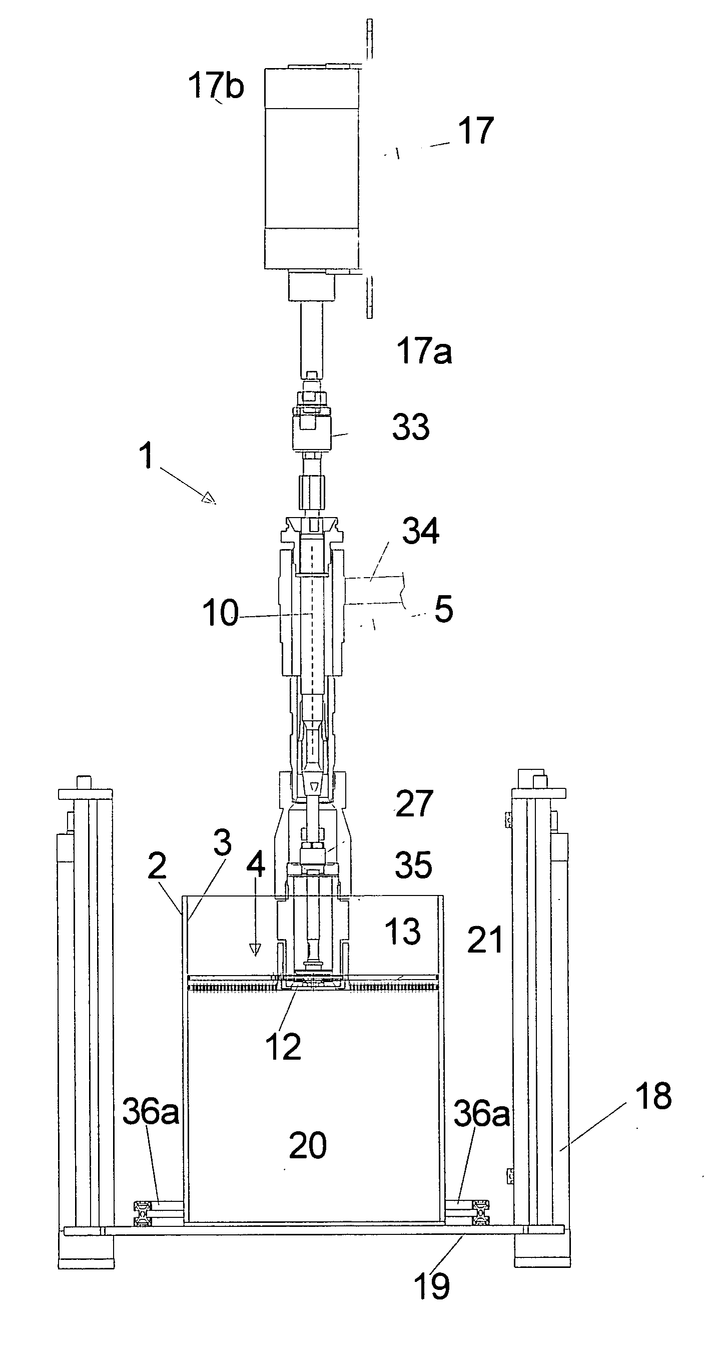
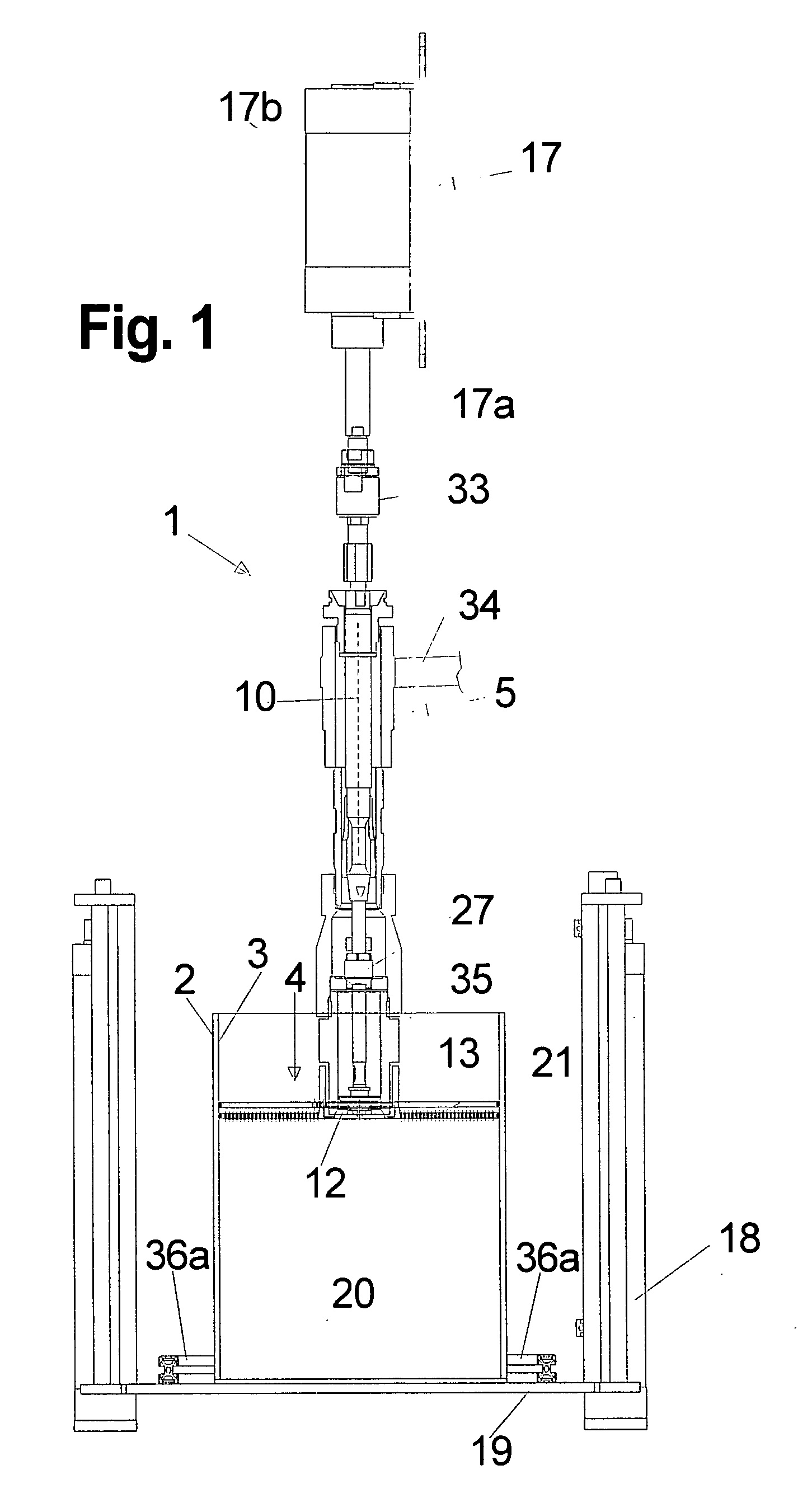
[0055]FIG. 1: the emptying device,

second embodiment

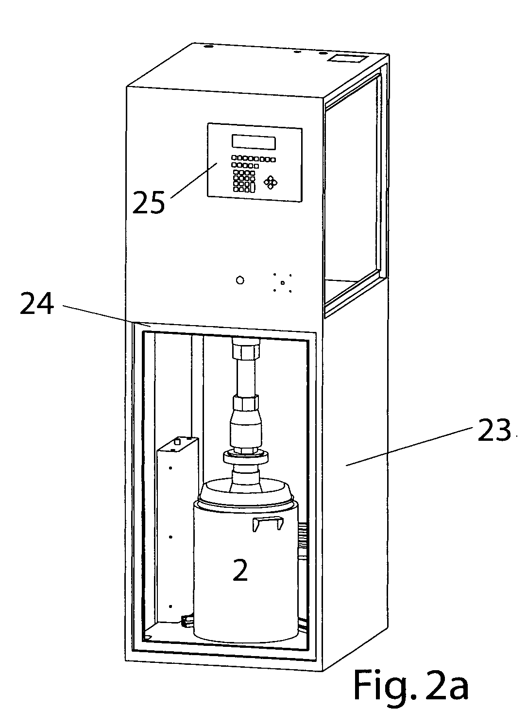
[0056]FIG. 2: the emptying device,

[0057]FIG. 3: The grid plate,

[0058]FIG. 4: The upper plate, and

[0059]FIG. 5: The drum follower plate assembled from the above.

[0060]FIG. 1 shows the emptying device 1 in a side view, for removing paste 20, which is delivered in a barrel shaped container 2 with an interior cross section 3 constant over its height and mostly round.

[0061] For this purpose a drum follower plate 4 is placed or pressed onto the surface 21 of the paste 20, covering the whole surface 21 and abutting tight to the interior cross section 3 of the container 2.

[0062] Through a central pump opening 12 in the follower plate 4 the paste 20 is pumped out through a pump 5, whereby the volume of paste 20 in the container 2 decreases and the follower plate 4 follows the descending surface 21, due to pressurization in feed direction 10, thus in axial direction into the container 2.

[0063] The pump 5 in this case is a scoop piston pump, whose scoop piston 27 moves up and down in feed...


PUM


Abstract

For bubble free emptying of pasteous substances from drum-shaped containers these are pumped out through a drum follower plate placed onto the paste. In a refinement, the drum follower plate is provided hollow with a lower grid plate and before the beginning of the pumping out process through evacuation of the hollow intermediary space air, possibly present under the drum follower plate, is sucked from there into the intermediary space, so that the pump scooping from below the grid plate only feeds pasteous material right from the beginning.

Description

I. AREA OF APPLICATION [0001] The invention regards an emptying device for highly viscous materials. II. TECHNICAL BACKGROUND [0002] Materials that are so viscous that, due to gravity, they do not let enclosed air bubbles exit upwards—also in large containers—, or the material does not continue to slide to the deepest spot any more, pose considerable difficulties, when this highly viscous material is to be fed out of a container e.g. through a pipe connection, so that no air bubbles are fed in the feed line, since this may cause problems in a subsequent application, e.g. when automatically applying a line of sealant or glue material. [0003] So far such pastes were transported and delivered in cylindrical buckets or drums, which were emptied by the user through pressing a so called drum follower plate onto the top surface of the paste with the drum opened, wherein a pump, e.g. a scoop piston pump was connected tight to a central pass through in the drum follower plate (drum follower ...

Claims


Application Information

Patent Timeline
IPC IPC(8): G01F13/00B65D88/54B67D7/02
CPCB05C11/10B67D7/645F04B23/028
Inventor SCHEUGENPFLUG, ERICH
Owner SCHEUGENPFLUG
Learn More