
Spatial simulation program and system

a technology of spatial simulation and simulation program, applied in the field of spatial simulation program and system, can solve the problems of inability to simulate an area that does not correspond to the target area, inability to easily calculate a spatial simulation for a larger target area with a standard computer, and inability to simulate an upstream area, etc., to achieve the effect of reducing the cost of executing the spatial simulation, reducing the amount of spatial data to be obtained, and high speed

Active Publication Date: 2007-02-08
HIATACHI POWER SOLUTIONS CO LTD
View PDF2 Cites 6 Cited by
  • Summary
  • Abstract
  • Description
  • Claims
  • Application Information

AI Technical Summary

Benefits of technology

[0006] This invention is made to solve the above problem. It is therefore an object of this invention to provide a program and a system for performing a spatial simulation at a high speed with a small amount of data so as to easily perform the spatial simulation for a large target area.
[0008] Therefore, this invention enables the spatial simulation at a high speed with a small amount of data for a large target area. Furthermore, the amount of spatial data to be obtained can be reduced by obtaining spatial data of a sub domain at the time when a variable in the sub domain is required to be updated as compared with a method of estimating necessary spatial data prior to the execution of a simulation and obtaining the spatial data at a time. As a result, when, for example, the spatial data is fare-paying, the cost for executing the spatial simulation can be reduced.

Problems solved by technology

However, in the conventional spatial simulation method as described above, it is necessary to first designate the target area, which makes it impossible to simulate an area that does not correspond to the target area.
For example, in the case of a flood simulation for simulating a downstream area of one river as a target area, it is impossible to simulate an upstream area, a middlestream area, and the other flooded area of the river, which are not selected as the target area.
Thus, there is a problem in increasing the target area because it is difficult to readily calculate a spatial simulation for a larger target area with a standard computer.

Method used


Image

  • Spatial simulation program and system
  • Spatial simulation program and system
  • Spatial simulation program and system

Examples


Embodiment Construction

[0025] Hereinafter, an embodiment, in which a spatial simulation according to this invention is applied to a flood simulation, will be described based on the accompanying drawings.

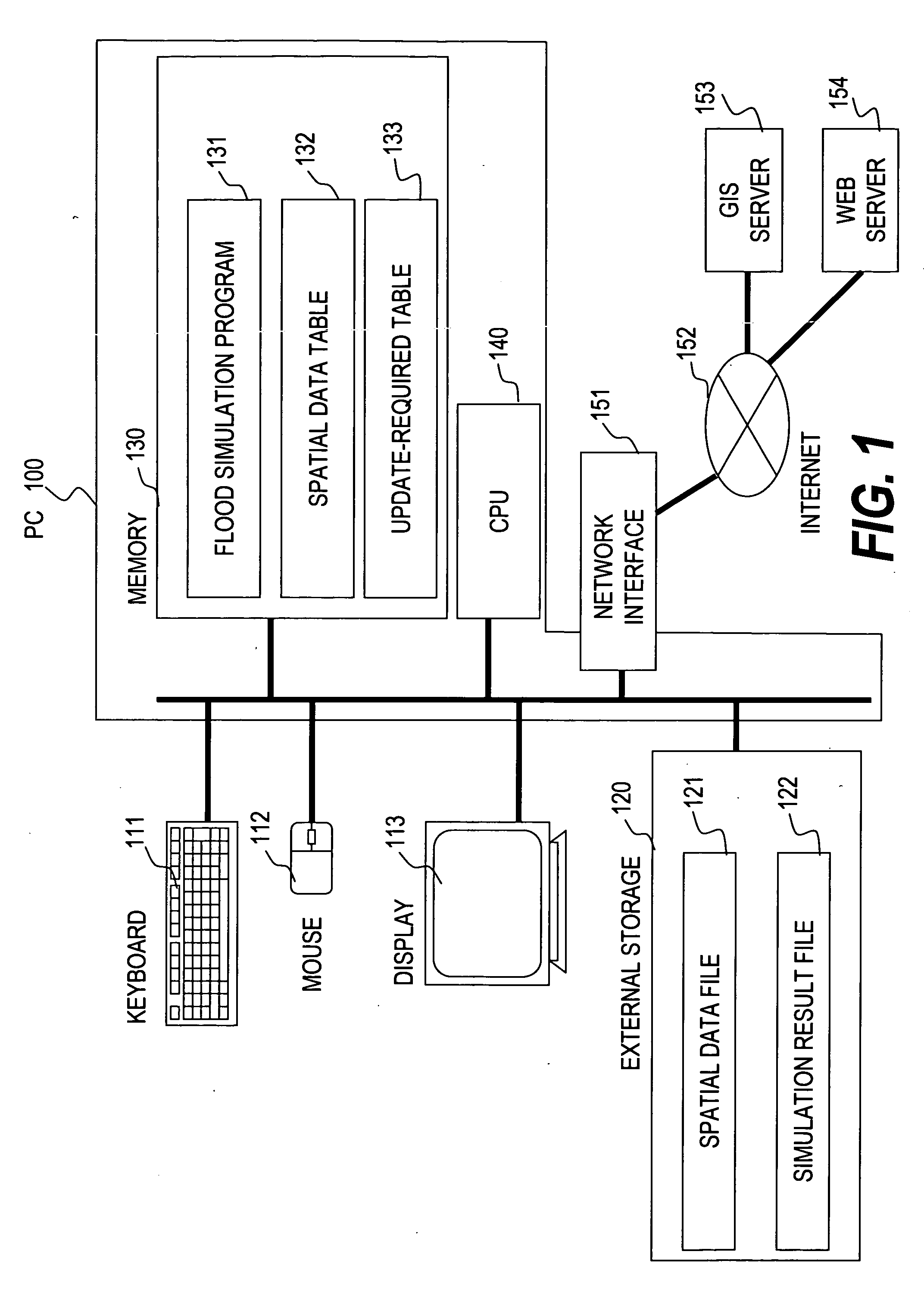
[0026]FIG. 1 is a schematic block diagram showing a configuration of a computer system for realizing a spatial simulation according to this invention.

[0027] A user of the spatial simulation inputs an instruction through an input unit such as a keyboard 111 or a mouse 112 connected to a PC (Personal Computer) 100. The result of the simulation is output to a display unit 113 so as to be confirmed. In the PC 100, a CPU (Central Processing Unit) 140 executes a flood simulation based on a flood simulation program 131 serving as a spatial simulation program loaded in a memory 130.

[0028] During the execution of the flood simulation program 131, a spatial data table 132 and an update-required table 133 are created and referred to in the memory 130. During the execution of the flood simulation program 131, the C...


PUM


Abstract

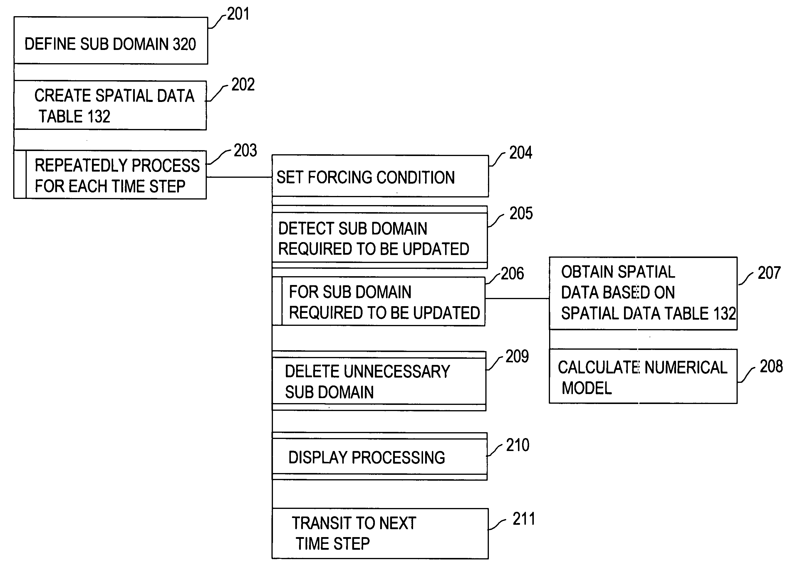
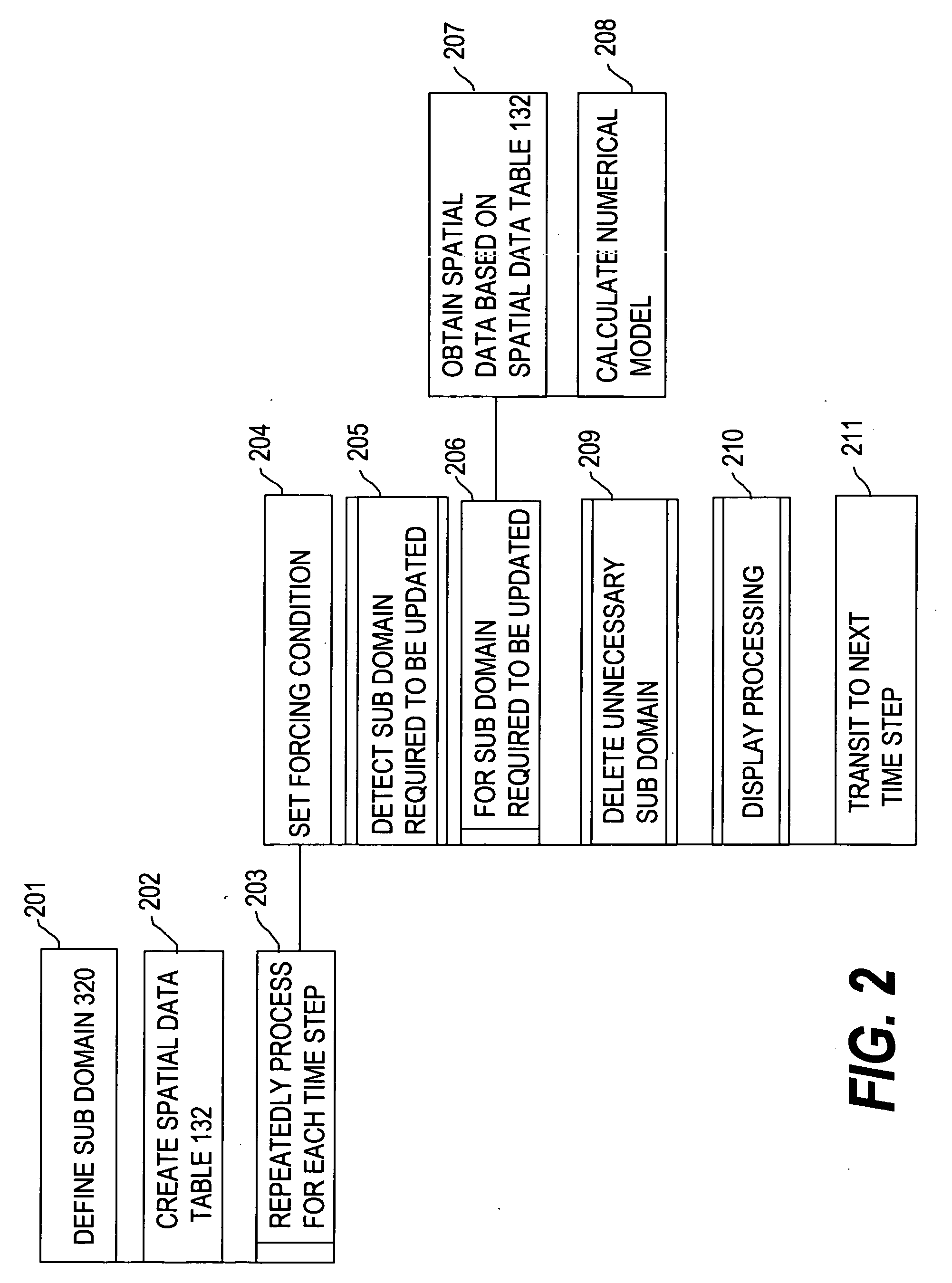
It is possible to easily perform the spatial simulation for a large area. Provided is a computer-readable medium recorded with a spatial simulation program for controlling a computer to execute procedures for calculating a time-based change of a variable in a plurality of numerical grids to reproduce on a computer a time-based change of a phenomenon represented by the variable in a space represented by the plurality of numerical grids, the spatial simulation program including the procedures of: defining a sub domain composed of the plurality of numerical grids (201); setting a forcing condition for the sub domain (204); detecting the sub domain including the numerical grid in which the variable changes with time; detecting the sub domain including the numerical grid in which the variable referred to for calculating the time-based change is positioned (205); and updating variables in the numerical grids constituting the detected sub domain (208).

Description

CLAIM OF PRIORITY [0001] The present application claims priority from Japanese application P2005-212458 filed on Jul. 22, 2005, the content of which is hereby incorporated by reference into this application. BACKGROUND OF THE INVENTION [0002] This invention relates to a simulation for reproducing an interesting phenomenon on a computer, in particular, a spatial simulation program and system for updating a variable in a numerical grid for each time step. [0003] Recently, for the purpose of grasping an interesting phenomenon, a system for easily realizing a spatial simulation on a standard computer such as a PC (Personal Computer) has been a focus of attention. In general, in the spatial simulation, a real space is represented by a plurality of numerical grids, and a phenomenon to be simulated is represented by a variable. Furthermore, a time-based change in the phenomenon is represented by updating the variable for each certain duration (time step). For example, a flood simulation wh...

Claims


Application Information

Patent Timeline
Patent Type & Authority Applications(United States)
IPC IPC(8): G06F17/10G06F19/00G06Q50/00G06Q50/26
CPCG06F17/5018G06F30/23
Inventor YAMAGUCHI, SATOSHIMURO, KEIROIWAMURA, KAZUAKI
Owner HIATACHI POWER SOLUTIONS CO LTD
Learn More