
Method and system for combining seismic data and basin modeling

Active Publication Date: 2007-02-08
LANDMARK GRAPHICS
View PDF4 Cites 26 Cited by
  • Summary
  • Abstract
  • Description
  • Claims
  • Application Information

AI Technical Summary

Benefits of technology

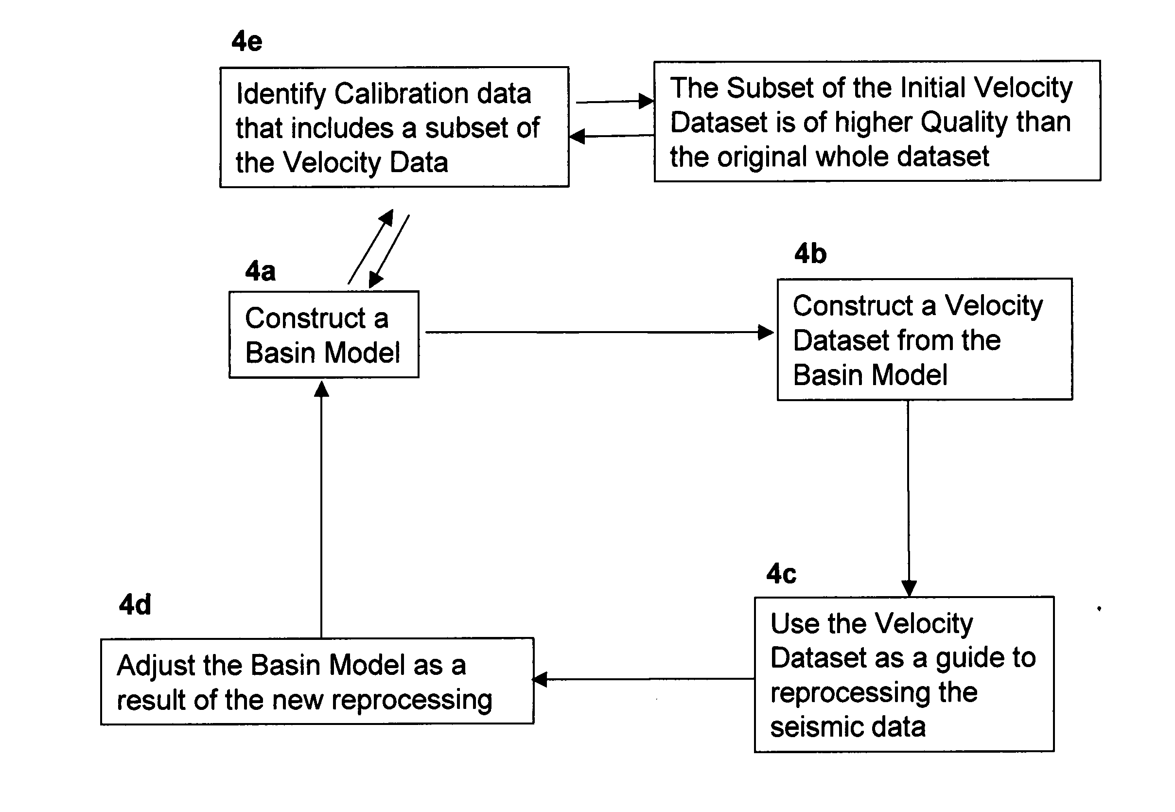
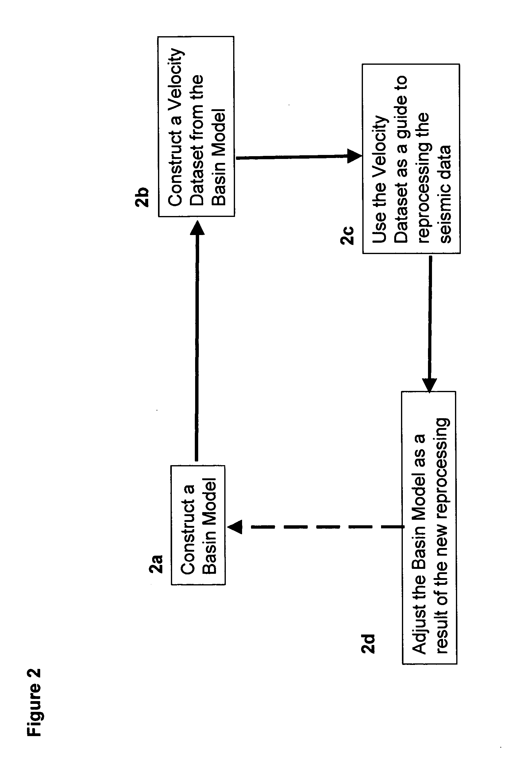
[0004] The present invention relates to methods and computer-related systems for processing seismic data through the use of information provided by basin modeling. More specifically, the present invention relates to methods for deriving an improved velocity field for the reprocessing seismic data through the analysis of some of the results derived from basin modeling. Thus, one aspect of the present invention relates to methods of providing an improved seismic dataset comprising the steps of providing an initial basin model, whereby the initial basin model is constructed using an initially-available dataset including at least some initially available seismic velocity data, and using a selected subset of the initially available seismic velocity data as calibration inputs; constructing a velocity dataset from the initial basin model; and reprocessing the initially available seismic data using the velocity dataset from the initial basin model as a guide.
[0005] Additional iterations of this method may be used to further improve the basic model. Another aspect of the present invention relates to computer-based systems for providing an improved seismic dataset comprising means for providing an initial basin model, means for constructing a velocity dataset using the initial basin model, means for identifying a selected subset of velocity data fro

Problems solved by technology

In the presence of overpressures, seismic velocities are lower than would normally be expected at that depth, amplitudes are suppressed and the presence of multiple pressure compartments and ramps makes the interpretation of velocities from seismic alone difficult.
Below salt masses, high velocity high reflectivity interfaces and below rugose surfaces, the Earth filter removes significant amounts of the signal that again makes the analysis of velocities from seismic data alone difficult.
Below about 15,000′ (different depths in different basins), the seismic velocities are high and the frequency content of the recorded signal becomes lower, again making the velocity analysis of the data from seismic alone difficult.

Method used


Image

  • Method and system for combining seismic data and basin modeling
  • Method and system for combining seismic data and basin modeling
  • Method and system for combining seismic data and basin modeling

Examples


Embodiment Construction

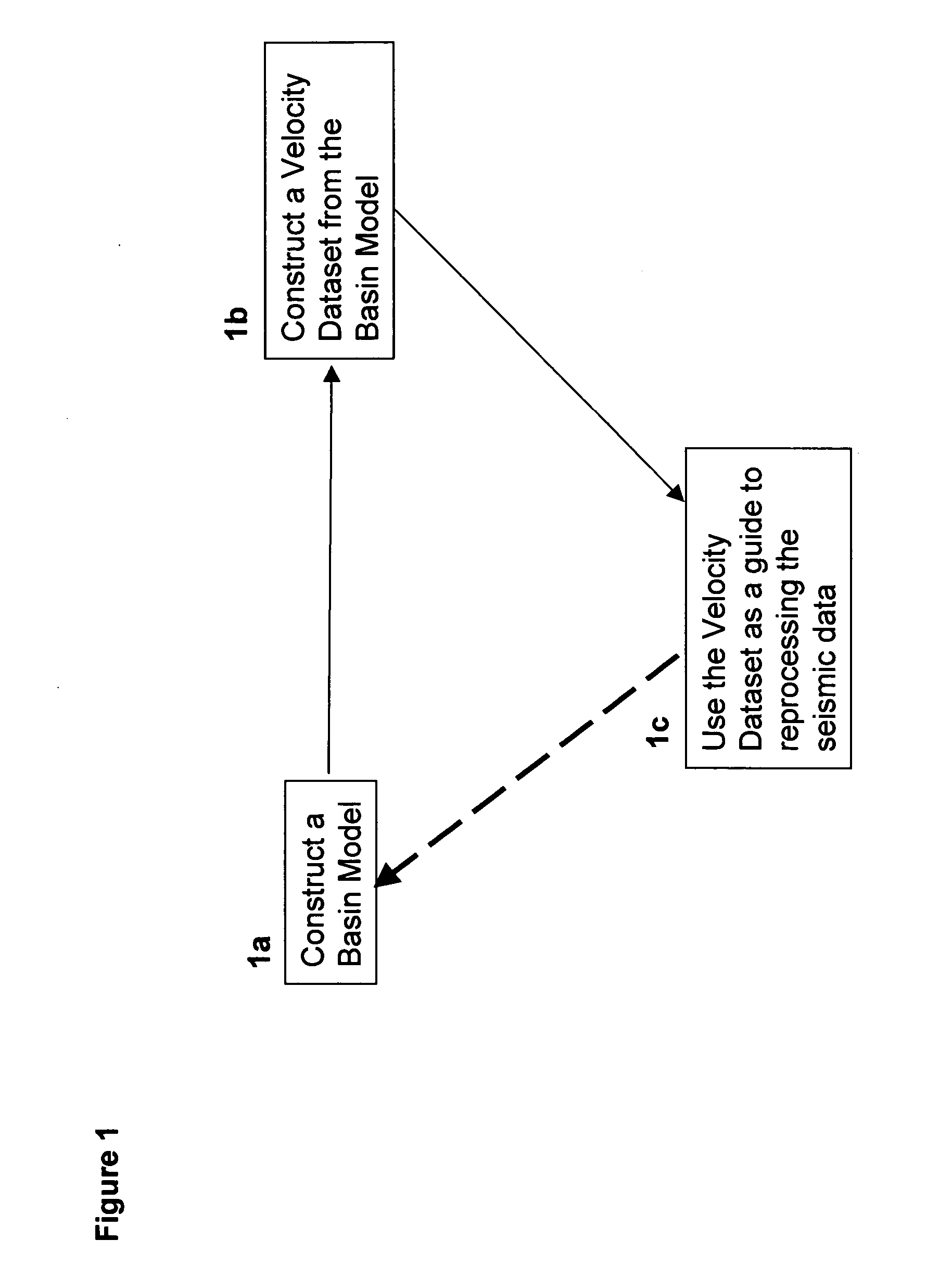
[0017]FIG. 1 represents a simple embodiment of the current invention and is comprised of the following steps: (1a) construction of an initial basin model using at least some seismic data, (1b) construction of a velocity dataset from the basin model, and (1c) use of this velocity cube as a guide to re-picking the velocities that will be used for reprocessing the seismic data. Typically, at least some seismic data will be available for constructing the initial basin model. Preferably, the initial basin model is constructed from all initially available seismic and other input and calibration data. Most preferably, at least some of the initially available data is well control data. The initial basin model is preferably constructed using known methods and calibrated to all the known geologic, seismic and well data in the modeled area. The basin model is then used to construct a velocity volume. This velocity volume that can then be used as a guide to re-picking the initially solely seism...


PUM


Abstract

Methods and computer-based systems are provided for processing seismic data through the use of information provided by basin modeling. Provided are methods and systems for providing an improved seismic dataset by means of providing an initial basin model constructed using an initially-available dataset including seismic velocity data; constructing a velocity dataset from the initial basin model; and reprocessing the initially available seismic data using the velocity dataset from the initial basin model as a guide. Also provided are methods and systems for predicting fluid pressure in a subsurface region of interest.

Description

BACKGROUND OF THE INVENTION [0001] The present invention concerns methods and systems for processing seismic data and basin modeling. A correct interpretation of the velocity field within the Earth is necessary to properly image seismic data at its true location and depth in the subsurface. This velocity field can be estimated by a number of methods, the most important and common being the analysis of stacking, or the roughly equivalent Normal Moveout (“NMO”), velocities on Common Midpoint (“CMP”) gathers. A number of other techniques are also used, including the use of multiple constant-velocity stacks of a small interval of the seismic line, signal coherency analysis of the velocity spectrum, horizon-consistent velocity analysis, the application of statics and residual statics corrections, migration velocity analysis and tomographic inversion techniques. In the absence of well data, these techniques rely on information that is contained within the seismic dataset itself for all of...

Claims


Application Information

Patent Timeline
IPC IPC(8): G01V1/28
CPCG01V2210/66G01V1/282
Inventor WILLIAMS, KENNETH E.
Owner LANDMARK GRAPHICS
Learn More