
Automatic candle snuffer

a candle snuffer and automatic technology, applied in the direction of burning process, extinguishing devices, lighting and heating apparatuses, etc., can solve the problems of excessive property damage, injury or death, and candles left burning

Inactive Publication Date: 2007-02-08
BURTON DAVID +2
View PDF46 Cites 15 Cited by
  • Summary
  • Abstract
  • Description
  • Claims
  • Application Information

AI Technical Summary

Benefits of technology

"The automatic candle snuffer is a device that can be attached to a jar to extinguish a candle after a set amount of time. It has a mechanical timer and a clamp to hold it in place. The device has a spring-driven gear housing with a timer and a return spring. The gear housing can be rotated to uncover the jar and light the candle. A release mechanism allows the gear housing to gradually cover the jar and deplete the oxygen, extinguishing the flame. The device can also be mounted within a decorative candle shade and has a timing mechanism to move a snuffing lid between an opening and covering position."

Problems solved by technology

When left unattended the open flame of a candle can cause a fire that has the potential to cause extensive property damage, and that can even result in injury or death.
While people often light candles with the intention of extinguishing them later, it is not uncommon that candles are left burning through being forgotten, or because the person who lit the candle has fallen asleep.
While this does limit the possibility of accidental contact with the flame by flammable materials, the risks associated with burning candies are not completely eliminated by enclosing the candle.
Unattended candles may be accidentally upset, exposing the flame and spilling hot wax, which results in a fire or burn hazard.
Also, when a candle burns inside a container for long periods of time, the container is heated, presenting a burn hazard and a possible source of ignition for a fire.

Method used


Image

  • Automatic candle snuffer
  • Automatic candle snuffer
  • Automatic candle snuffer

Examples


Embodiment Construction

[0025] The present invention is an automatic candle snuffer for extinguishing a lit candle automatically after an interval of time. The candle snuffer employs a spring that is wound by the user. When the spring unwinds, a gear train is triggered to close the mouth of a jar housing the burning candle.

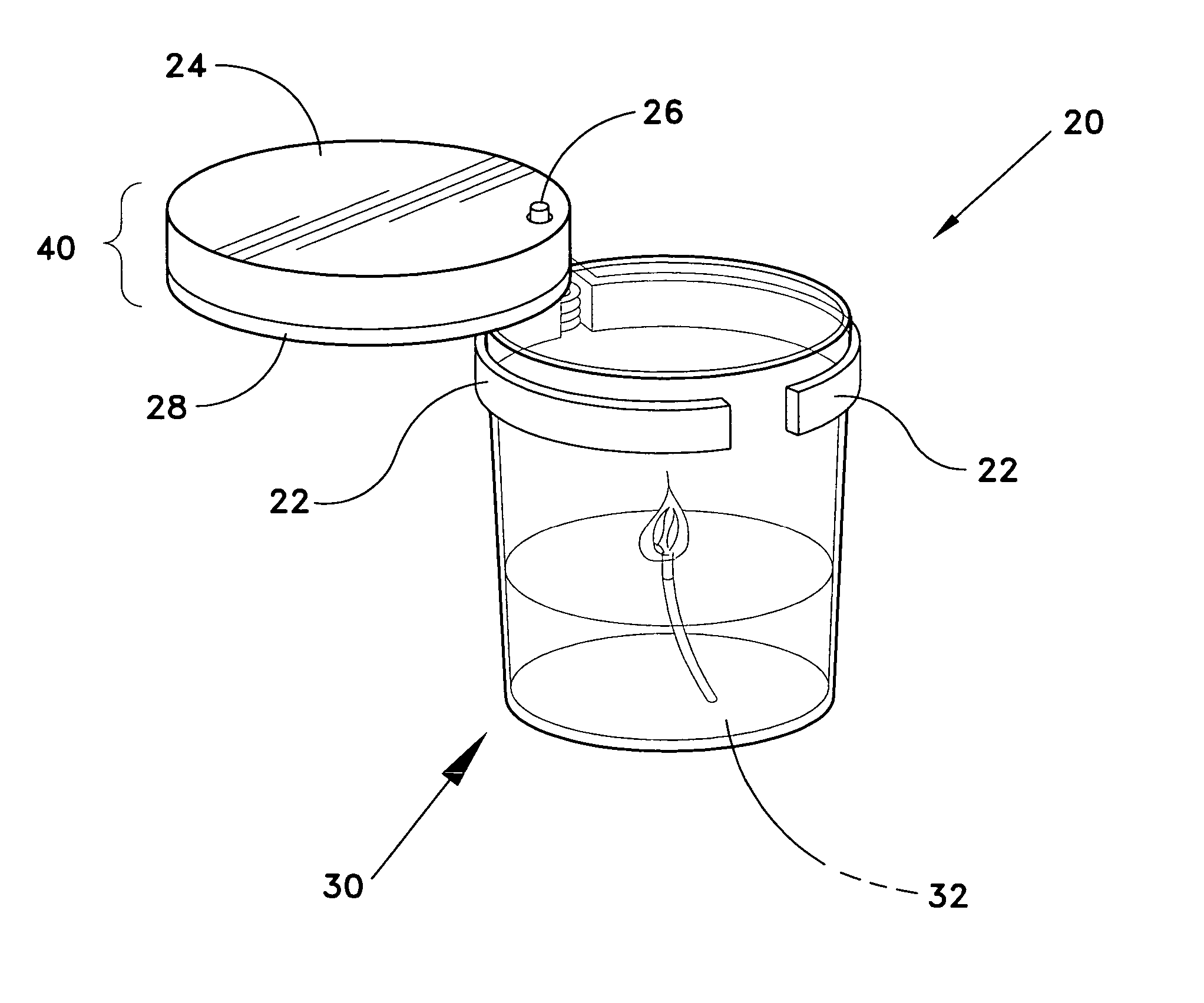
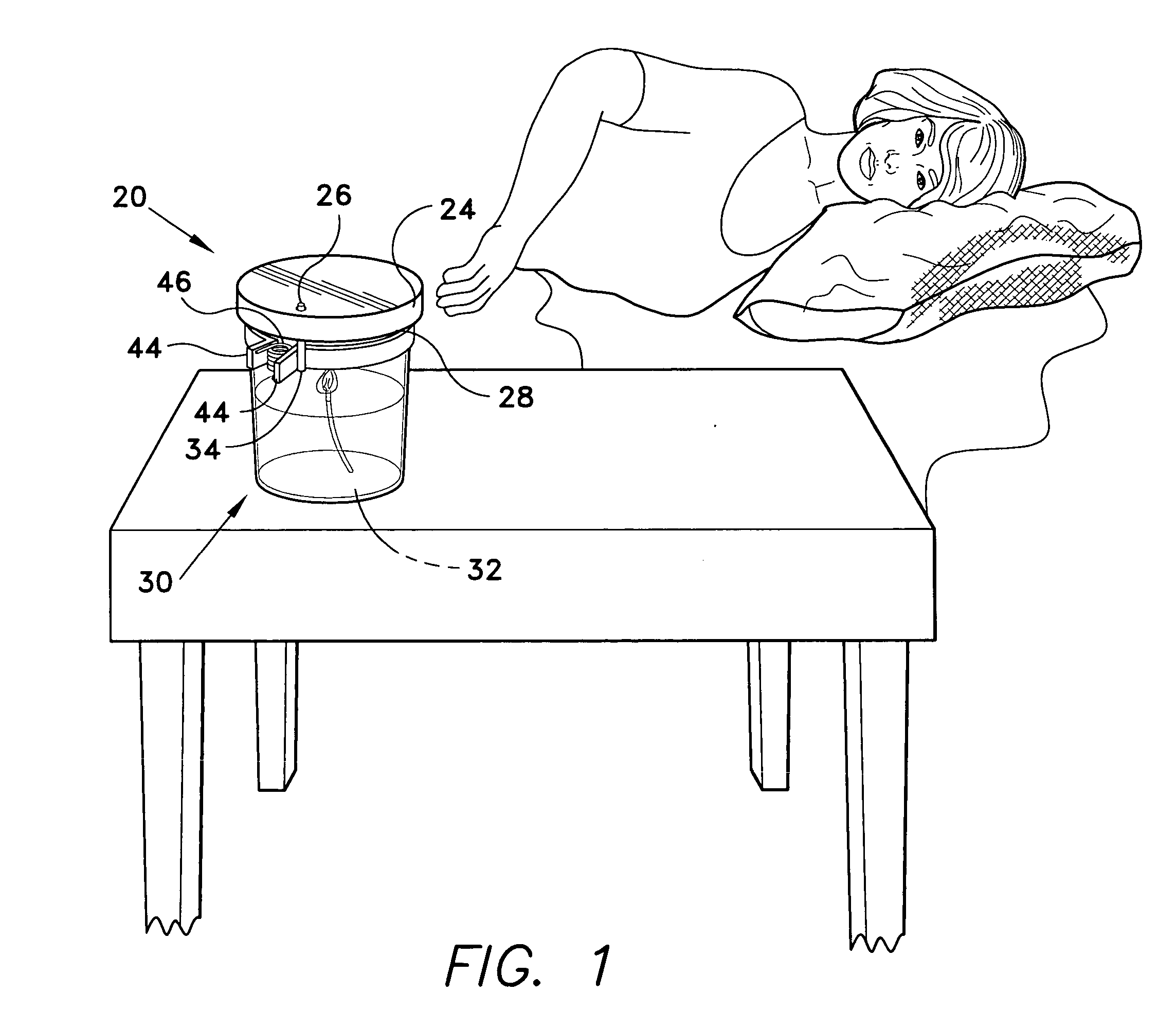
[0026] A first embodiment of the invention is shown in FIGS. 1-4. Referring first to FIG. 1, an automatic candle snuffer 20 is shown attached to a jar 30 containing a candle 32. The candle snuffer 20 is attached to the mouth of the jar 30 via a clamp. In FIG. 1, the candle snuffer 20 is shown in the closed position. The candle snuffer 20 includes a gear housing having an upper gear housing 24 and a lower gear housing 28. A reset pin 26 extends through an opening in the upper gear housing 24.

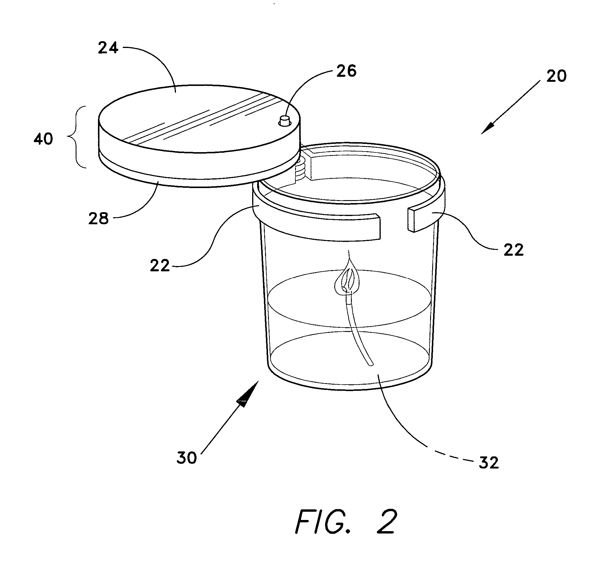
[0027]FIG. 2 shows the candle snuffer 20 in the open position. The gear housing 40, which comprises the upper gear housing 24 and the lower gear housing, serves as the closing portion of the candle ...


PUM


Abstract

The automatic candle snuffer is a mechanical timer driven device that extinguishes a candle in a jar after a user selectable time interval. A clamp mounts the candle snuffer to the mouth of the jar. The snuffing mechanism is a spring driven gear housing shaped to cover the mouth of the jar in the closed position, but which rotates around a stationary pin to uncover the jar. The gear housing contains a spring-driven timer, which drives a plurality of gears. Rotating the upper portion of the gear housing relative to the lower portion winds a timing spring, while rotating the entire housing around the pivot pin uncovers the mouth of the jar and winds a return spring. When the timer spring is unwound, a release mechanism frees the gear housing allowing the return spring to rotate the gear housing until the mouth of the jar is covered.

Description

BACKGROUND OF THE INVENTION [0001] 1. Field of the Invention [0002] The present invention relates to candle accessories, and in particular, to an automatic candle snuffer that extinguishes a candle automatically after a preset interval. [0003] 2. Description of the Related Art [0004] Although electric lighting displaced the use of candles as the main source of lighting in the late 19th century, candles are still very frequently used. Candles are used to provide lighting during emergency situations when the normal supply of electrical power is interrupted, and also to add mood or ambiance to a setting during seasonal celebrations, or at other times when it is desired to establish an atmosphere. Scented candles are used to provide fragrances to a room for festive and other special occasions. Some candles are provided with special chemicals that are purported to provide therapeutic benefits when the chemicals are released through burning the candles. For all of the above reasons, the u...

Claims


Application Information

Patent Timeline
Patent Type & Authority Applications(United States)
IPC IPC(8): F23Q25/00
CPCF23Q25/00
Inventor BURTON, DAVIDSALMON, JAY R.HAYES, ROBERT
Owner BURTON DAVID
Learn More