Automatic liquid metering apparatus

Inactive Publication Date: 2007-02-08
HUANG SHIH YEN +1
View PDF11 Cites 25 Cited by
  • Summary
  • Abstract
  • Description
  • Claims
  • Application Information

AI Technical Summary

Benefits of technology

[0006] The primary object of the present invention is to provide an automatic liquid metering apparatus which allows precision metered supply of liquid concentrate and diluting water through microprocessor programming to meet user's needs for quick, metered and sanitary dispensing of beverage.
[0007] To achieve the aforesaid objects, the automatic liquid metering apparatus of the present invention features a control process with a microprocessor to control the running time of motor pump, check valves and a lift mechanism, characterized in which the concentrate supply of the metering apparatus is connected to the inlet of motor pump via a tubing, the diameter of pump inlet is greater than that of pump outlet, and the pump outlet is connected to an internal tubing of lift mechanism via a check valve. When the motor stops running, the check valve is closed to stop the fluid from leaking or backflow due to siphonage. Also, with the inlet size of concentrate pump being greater than its outlet that more liquid comes in than discharge, it totally prevents the uneven flow of concentrated liquid in the pump caused by the presence of vacuum inside. The pump is akin to a syringe that draws in fluid rapidly and creates vacuum in the process before the syringe is completely filled. For the pumping of diluting water, regular pump or solenoid valve will work due to the better fluidity of diluting water. With the metered supply of liquid concentrate and diluting water, consumers can press the desired buttons to get the properly diluted drink.
[0008] Another feature of the present invention provides a new design, characterized in which the metering apparatus is disposed with at least a liquid pump connected to a concentrate tubing and a diluting water pump connected to a diluting water tubing. The outlets of the pumps are respectively connected to the outlet of liquid concentrate and diluting water via a check valve tubing. A motor-run lift mechanism is provided at the outlet that ascends or descends according to the button selected for small cup, medium cup or large pot, and stops when the positioning point switch for the selected cup or pot is touched under the control of microprocessor. This design prevents the spurting of dispensed fluid into the cup or pot due to long distance between the outlets of liquid concentrate and diluting water and the rim of cup or pot. The provision of a lift mechanism at the fluid outlet to ensure sanitary and smooth dispensing is a feature of the invention.
[0009] In addition, when the concentrate pump stops pumping, there will be some liquid concentrate remaining at the outlet of tubing and forming a semi-sphere shaped drop there. After some time later, say ten minutes or more, the semi-sphere shaped drop of liquid concentrate will start drying out from its appearance due to air flow and temperature. As a result, liquid concentrate will tend to spray toward everywhere when next time the concentrate pump is working again. Therefore, the present invention discloses a pressing mechanism which will compress part of the tubing to squeeze some remaining liquid concentrate out of the outlet, and then let the tubing returning back its original circular shape so as to suck the liquid concentrate located at the outlet back to the interior of tubing. As a result, there will be no more semi-sphere shaped drop remaining at the outlet of tubing. The outlet will become a plane and thus the remaining liquid concentrate inside the tubing will not be easily influenced by the drying effect due to air flow or temperature. Therefore, the liquid concentrate will flow smoothly and vertically toward the cup every time when the concentrate pump operates.

Problems solved by technology

As a result, liquid concentrate will tend to spray toward everywhere when next time the concentrate pump is working again.

Method used


Image

  • Automatic liquid metering apparatus
  • Automatic liquid metering apparatus
  • Automatic liquid metering apparatus

Examples


Embodiment Construction

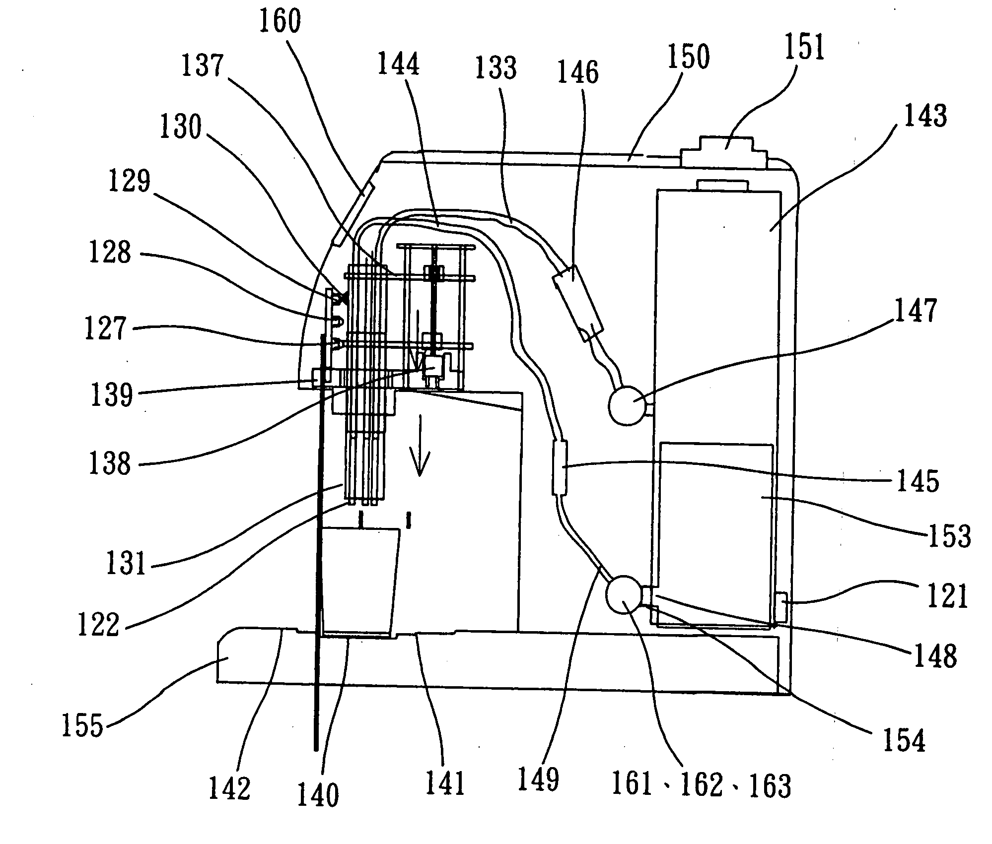
[0019] The automatic liquid metering apparatus of the invention features the use of microprocessor for precision control of motor pumps and check valves. In the process of drawing and discharging fluid, the running time of motor pump is under microprocessor control to supply precise amounts of liquid concentrate and diluting water for mixing. In the pump for liquid concentrate with less fluidity, its inlet is designed with larger diameter than its outlet such that sufficient amount of liquid is drawn in instantly without creating a vacuum state that causes unstable flow. The control process is linked up in the following fashion: the outlet of liquid concentrate is connected to the inlet of motor pump via a tubing; the outlet of motor pump is connected to the outlet of concentrate jacket assembly of lift mechanism via a check valve tubing; the outlet of diluting water tank is connected to the inlet of motor pump via a pump tubing; the pump outlet tubing is connected to the outlet of ...


PUM

PropertyMeasurementUnit
Diameteraaaaaaaaaa
Heightaaaaaaaaaa
Distanceaaaaaaaaaa

Abstract

An automatic liquid metering apparatus is disposed with at least a liquid concentrate motor pump with a tube connected thereto and at least a diluting water motor pump with a tube connected thereto where the turning of the pumps is timed by a microprocessor to control the amounts of liquid concentrate and diluting water to be dispensed. The outlet tubing of the pump is connected to the outlet of liquid concentrate and diluting water via a check valve. A lift mechanism is provided at the concentrate / diluting water outlet, which allows the choice of small cup, medium cup or large pot by ascending or descending to the proper height. The stop point of the lift mechanism is microprocessor controlled to prevent the spurting of dispensed liquid concentrate and diluting water due to great distance between their outlet and the rim of cup to ensure sanitary and smooth dispensing of fluids. This invention features precision dispensing of concentrate and diluting water and low manufacturing costs.

Description

BACKGROUND OF INVENTION [0001] 1. Field of the Invention [0002] The advent of biotechnology allows 5 grams of beverage concentrate to be made into 150 grams of drink. Thus a liquid metering apparatus needs to be designed with precision microprocessor to meet the consumer demands. The new metering apparatus design disclosed in this invention features a concentrate pump and a diluting water pump with respective outlet connected to the outlet of liquid concentrate and diluting water via a check value tubing. The pump outlet is disposed with at least a set of lift mechanism that ascends or descends in response to the rotation of pump motor which is under microprocessor control by the choice of small cup, medium cup or large pot. The vertical position of the small cup, medium cup and large pot as elevated or dropped by the lift mechanism is determined by the contact stop point as controlled by the rotation of pump motor, so liquid concentrate and diluting water dispensed into the cup or ...

Claims


Application Information

Patent Timeline
IPC IPC(8): B65B1/04B67D5/08B67D5/56B67D7/08B67D7/74
CPCB67D1/0036B67D1/1245B67D2001/0812B67D1/1256B67D1/1247
Inventor HUANG, SHIH YENCHEN, CHIUAN YUAN
Owner HUANG SHIH YEN
Why Eureka
Try Eureka