
Dust collector for autonomous floor-cleaning device

a technology for cleaning devices and dust collectors, which is applied in cleaning equipment, filtration separation, and separation processes, etc., can solve the problems of difficult detachment of the cover shells of the inside parts the design of the autonomous floor cleaning robot is still not satisfactory in function, and the housekeeper's labor to clean the floor with a hand-operated vacuum cleaner is hard to achieve the effect of easy cleaning and inexpensive manufacturing

Inactive Publication Date: 2007-02-08
YAN JASON
View PDF7 Cites 136 Cited by
  • Summary
  • Abstract
  • Description
  • Claims
  • Application Information

AI Technical Summary

Benefits of technology

[0005] The present invention has been accomplished under the circumstances in view. It is the main object of the present invention to provide a dust collector for autonomous floor-cleaning device, which is easy to clean and inexpensive to manufacture. To achieve this and other objects of the present invention, the dust collector is mounted in the air flowing path inside an autonomous floor-cleaning device, comprising a container, a partition member, and a filter member. The container comprises a container body, and a top cover shell attached to the container body and defining with the container body an inside space. The container body has a first suction hole and a second suction hole for guiding air into the inside space. The top cover shell has an air outlet for guiding air out of the inside space. The partition member is horizontally positioned in the container body, dividing the inside space of the container into an upper storage chamber and a bottom storage chamber. The partition member has a through hole in air communication between the first suction hole and the air outlet. The filter member is set between the through hole of the partition member and the air outlet of the top cover shell and adapted to remove dust from air passing through the upper storage chamber.

Problems solved by technology

It is a hard labor to a housekeeper to clean the floor with a hand-operated vacuum cleaner.
However, this design of autonomous floor-cleaning robot is still not satisfactory in function.
Because the cover shells are fastened together with screws, it is complicated to detach the cover shells for cleaning the inside parts of the autonomous floor-cleaning robot.
Further, the design of the grooves at the cover shells and the use of the packing rubber at the grooves to maintain an airtight status greatly increase the manufacturing cost of the robot.

Method used


Image

  • Dust collector for autonomous floor-cleaning device
  • Dust collector for autonomous floor-cleaning device
  • Dust collector for autonomous floor-cleaning device

Examples


Embodiment Construction

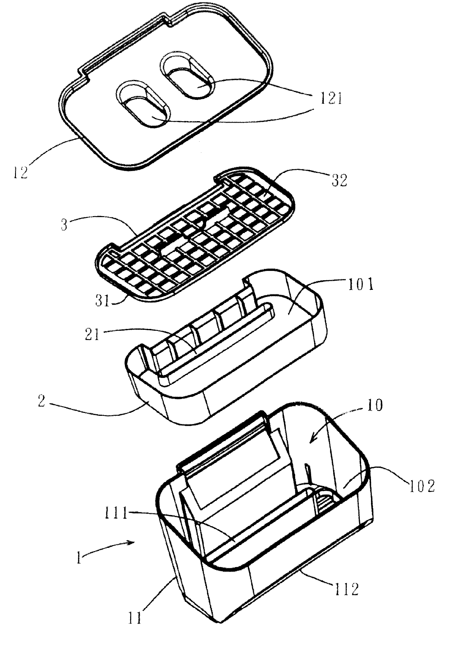
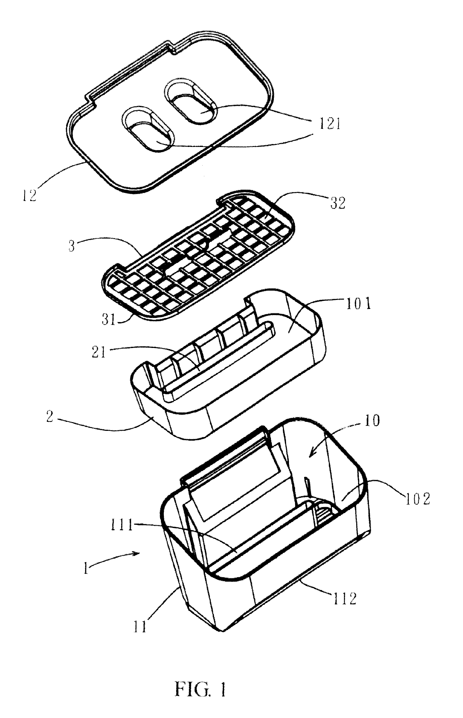
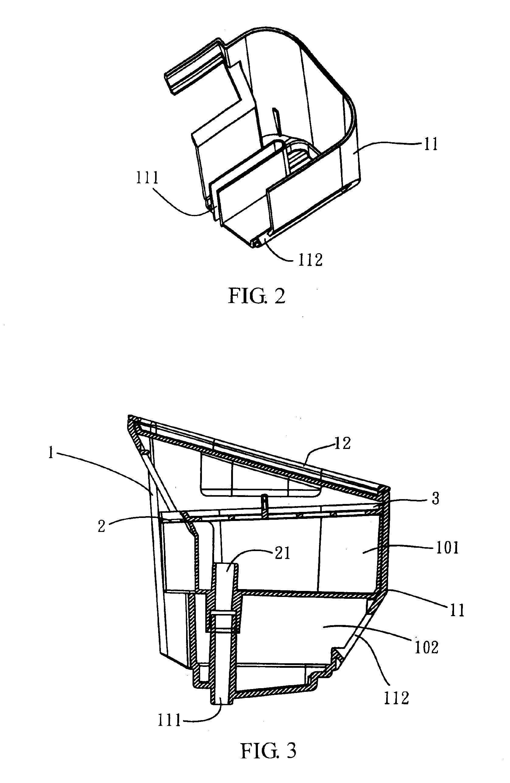
[0009] Referring to FIGS. 1˜3, a dust collector in accordance with the present invention is shown comprised of a container 1, a partition member 2, and a filter member 3.

[0010] The container 1 comprises a container body 11 and a top cover shell 12 detachably fastened to the container body 11 to close the top open side of the container body 11 by means of friction resistance. The container 1 defines therein an inside space 10. The container body 11 has a first suction hole 111 and a second suction hole 112. The top cover shell 12 has an air outlet 121. During operation of the autonomous floor-cleaning device (not shown) in which the dust collector is installed, air flows into the inside space 10 through the first suction hole 111 and the second suction hole 112 and then flows out of the inside space 10 through the air outlet 121.

[0011] The partition member 2 is shaped like a flat box fitting the container body 11. The partition member 2 is horizontally positioned in the container b...


PUM

PropertyMeasurementUnit
Areaaaaaaaaaaa

Abstract

A dust collector for use in an autonomous floor-cleaning device is disclosed to include a container, which is formed of a container body and a top cover shell and has two bottom suction holes and a top air outlet, a box-like partition member, which divides the inside space of the container into a bottom storage chamber and an upper storage chamber and has a through hole in communication between one bottom suction hole and the air outlet, and a filter member set between the through hole of the partition member and the air outlet of the container for removing dust from air passing through the upper storage chamber.

Description

BACKGROUND OF THE INVENTION [0001] 1. Field of the Invention [0002] The present invention relates to dust collecting apparatus and more particularly to a dust collector for use in an autonomous floor-cleaning device. [0003] 2. Description of the Related Art [0004] It is a hard labor to a housekeeper to clean the floor with a hand-operated vacuum cleaner. In recent years, many autonomous floor-cleaning devices have been disclosed and have appeared on the market. U.S. Pat. No. 6,883,201 discloses an autonomous floor-cleaning robot that is operable without human intervention to clean designated areas. As shown in FIG. 5A of the specification of said patent, the autonomous floor-cleaning robot has a top cover shell and a bottom cover shell fastened together with screws, and a backwall member 86BW that divides the inside space into a first storage chamber 86SC1 and a second storage chamber 86SC2. The first storage chamber 86SC1 is for the macroscopic and microscopic particulates swept up...

Claims


Application Information

Patent Timeline
IPC IPC(8): B01D46/00
CPCA47L9/122A47L9/102
Inventor YAN, JASON
Owner YAN JASON
Learn More