Optical recording and playback apparatus

Inactive Publication Date: 2007-02-01
SAMSUNG ELECTRONICS CO LTD
View PDF9 Cites 1 Cited by
  • Summary
  • Abstract
  • Description
  • Claims
  • Application Information

AI Technical Summary

Benefits of technology

[0009] Therefore, an aspect of the invention provides an optical recording and playback apparatus constructed such that a disc is prevented from being ejected from the optical recording and playback apparatus during operation of the optical recording and playback apparatus.

Problems solved by technology

When an external impact is applied to the optical recording and playback apparatus during an operation of the optical recording and playback apparatus, however, the disc, which is being rotated at high speed, may be separated from the drive unit and then ejected from the optical recording and playback apparatus through the gap between the entrance of the main body and the tray, by which users may be injured.
Since recent optical recording and playback apparatuses are capable of operating at a 52×X speed recording operation, in which the disc is rotated at 10,000 rpm or higher, a possibility of injury is increased.
Consequently, relatively easily opening the front door from the outside of the front door by a user is possible, and, therefore, a possibility of injury is not completely eliminated.

Method used


Image

  • Optical recording and playback apparatus
  • Optical recording and playback apparatus
  • Optical recording and playback apparatus

Examples


first embodiment

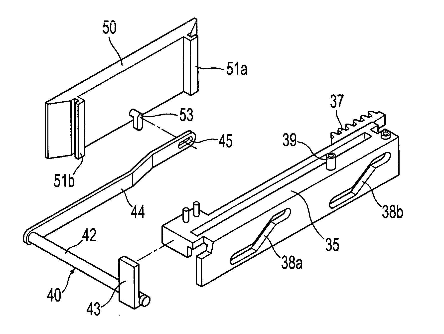
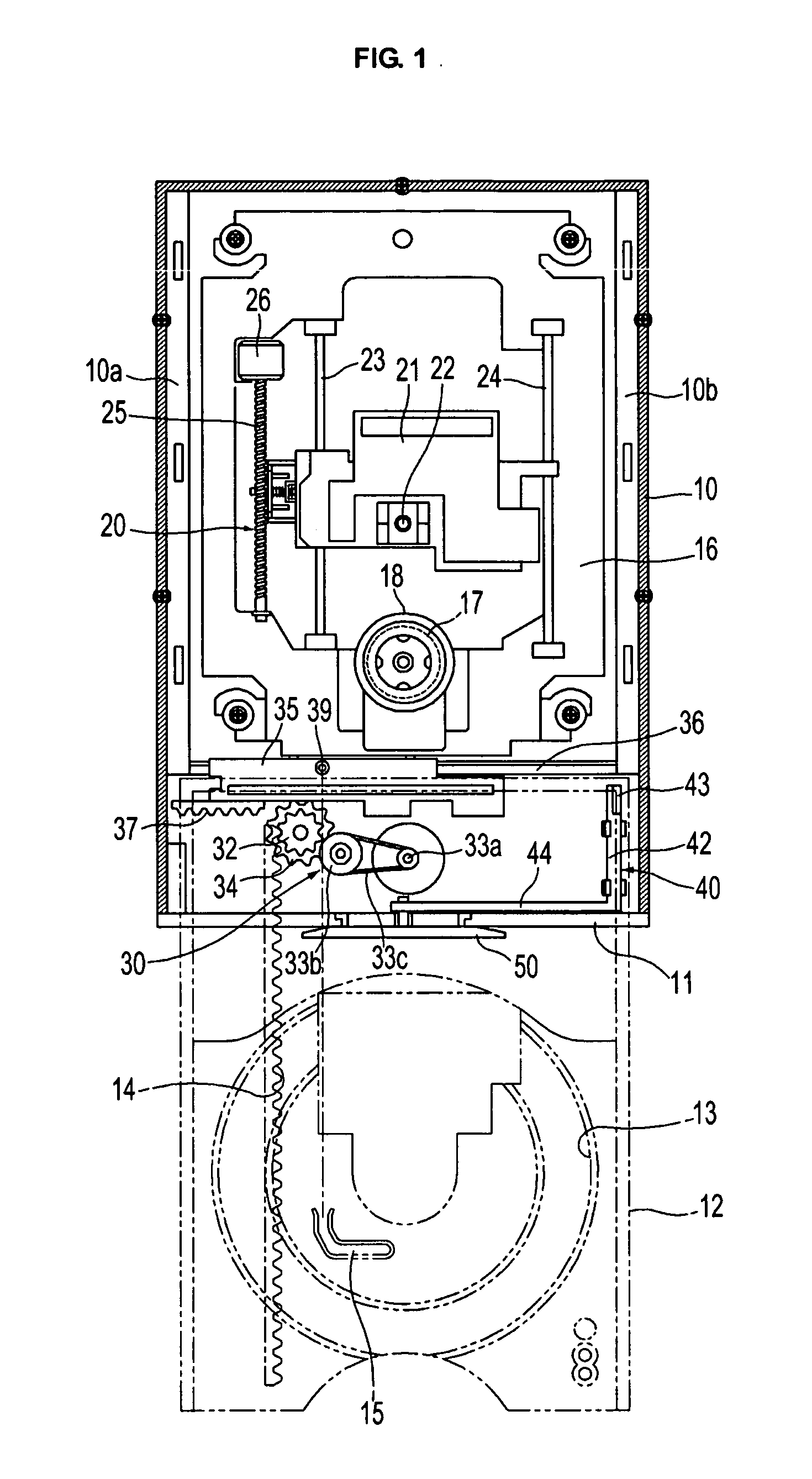
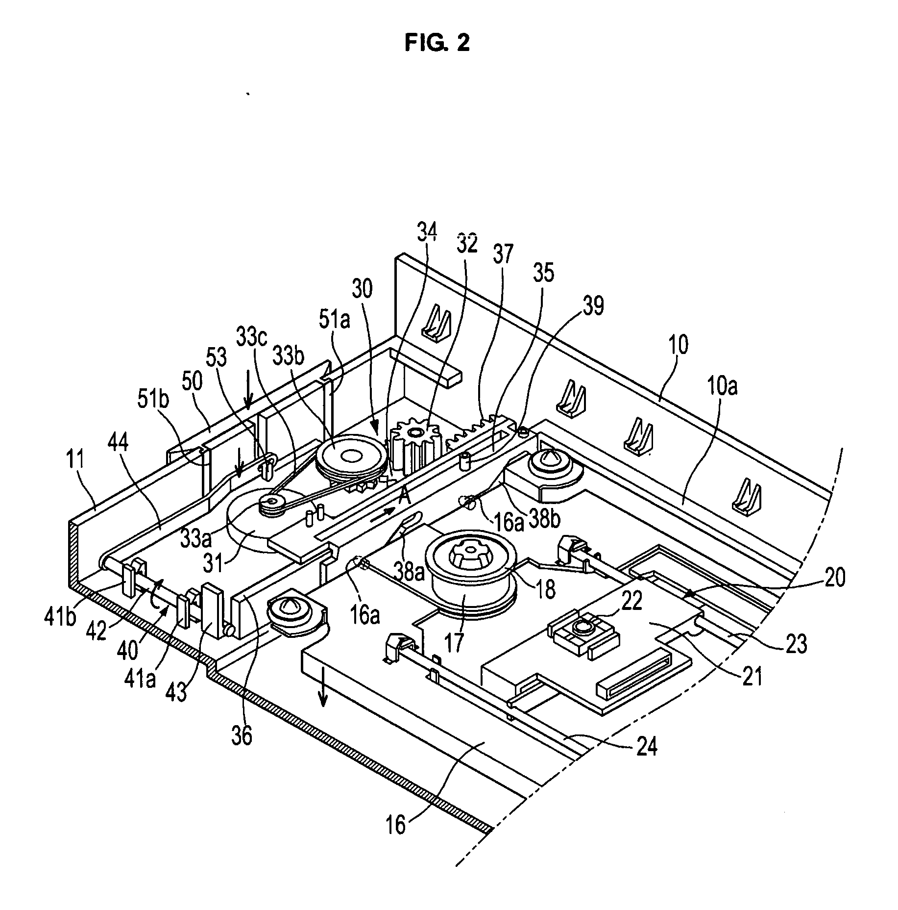
[0026] Referring to FIGS. 1 to 4, an optical recording and / or playback apparatus, according to the present invention, is illustrated. As shown in FIGS. 1 and 2, the optical recording and playback apparatus includes a main body 10, having an entrance 11 formed at the front surface thereof, and a tray 12 configured such that the tray 12 may be inserted into and / or ejected from the main body 10 through the entrance 11 of the main body 10. The optical recording and playback apparatus further includes a loading unit 30 to insert or eject the tray 12 into or from the main body 10, a deck 16 mounted in the main body such that the deck 16 may be moved upward and downward, a spindle motor 17 and an optical pickup unit 20 mounted at the deck 16, and a safety door 50 to close the entrance 11 after the tray 12 is inserted into the main body 12.

[0027] The tray 12 has a disc location part 13 formed at the upper surface thereof such that a disc (not shown) may be located on the disc location part ...

second embodiment

[0041] In the second embodiment, as shown in FIG. 5, when the movable member 61 is moved in the direction indicated by an arrow C according to the operation of the solenoid drive part 65, the safety door 50 is lowered to open the entrance 11 of the main body 10. When the movable member 61 is moved in the direction indicated by an arrow D according to the operation of the solenoid drive part 65, as shown in FIG. 6, on the other hand, the safety door 50 is raised to close the entrance 11 of the main body 10.

[0042] Consequently, when the sensors 71 and 72 sense that the tray 12 is completely inserted into the main body 10, the solenoid drive part 65 is operated to close the safety door 50. Specifically, the entrance 11 of the main body 10 is closed by the safety door 50 while the apparatus is operated after the tray 12 is inserted into the main body. Consequently, the disc is prevented from being ejected from the main body 10 during operation of the optical recording and playback appar...


PUM


Abstract

An optical recording and / or playback apparatus in which a disc is prevented from being ejected from the optical recording and playback apparatus during operation of the optical recording and playback apparatus. The optical recording and playback apparatus includes a main body having an entrance, a deck mounted in the main body and having a spindle motor and an optical pickup unit, a tray mounted at the main body such that the tray is inserted into or ejected from the main body through the entrance, a loading unit to insert or eject the tray into or from the main body, and a safety door mounted at the entrance to close the entrance after the tray is inserted into the main body, the safety door being opened and closed according to the operation of the loading unit.

Description

CROSS-REFERENCE TO RELATED APPLICATIONS [0001] This application claims the benefit of Korean Application No. 2005-67849, filed Jul. 26, 2005, in the Korean Intellectual Property Office, the disclosure of which is incorporated herein by reference. BACKGROUND OF THE INVENTION [0002] 1. Field of the Invention [0003] An aspect of the present invention relates to an optical recording and playback apparatus, and, more particularly, to an optical recording and playback apparatus including a safety door to prevent a disc from being ejected from the optical recording and playback apparatus during operation of the optical recording and playback apparatus. [0004] 2. Description of the Related Art [0005] An optical recording and playback apparatus is an apparatus that is capable of reading information, such as audio, video, and data, from a disc and recording the information to the disc. The optical recording and playback apparatus is generally used in computers or digital electric home applian...

Claims


Application Information

Patent Timeline
IPC IPC(8): G11B17/04
CPCG11B17/0405G11B33/027G11B17/056G11B17/04
Inventor LEE, KEUN HOLEE, JEUNG RAKLEE, YONG HOONYIM, HONG KYUNEUM, JAE YONG
Owner SAMSUNG ELECTRONICS CO LTD
Why Eureka
Try Eureka