Ink ribbon cassette

a technology of tape and tape loop, which is applied in the direction of printing, inking apparatus, printing mechanisms, etc., can solve the problems of poor image printing on recording paper, and achieve the effects of reducing the deviation of timing, high accuracy, and reducing the deviation of feeding the recording paper

Inactive Publication Date: 2007-01-25
ALPS ALPINE CO LTD
View PDF5 Cites 1 Cited by
  • Summary
  • Abstract
  • Description
  • Claims
  • Application Information

AI Technical Summary

Benefits of technology

[0025] According to a preferred embodiment, the ink ribbon cassette guides a recording paper during printing by paper guides to reduce the deviation of the timing in which the recording paper is nipped by the paper feed roller and thus reduces the feeding deviation of the recording paper during printing to perform an image print with high accuracy.

Problems solved by technology

Therefore, there is an undesirable possibility that a poor image is printed on the recording paper.

Method used


Image

  • Ink ribbon cassette
  • Ink ribbon cassette
  • Ink ribbon cassette

Examples


Embodiment Construction

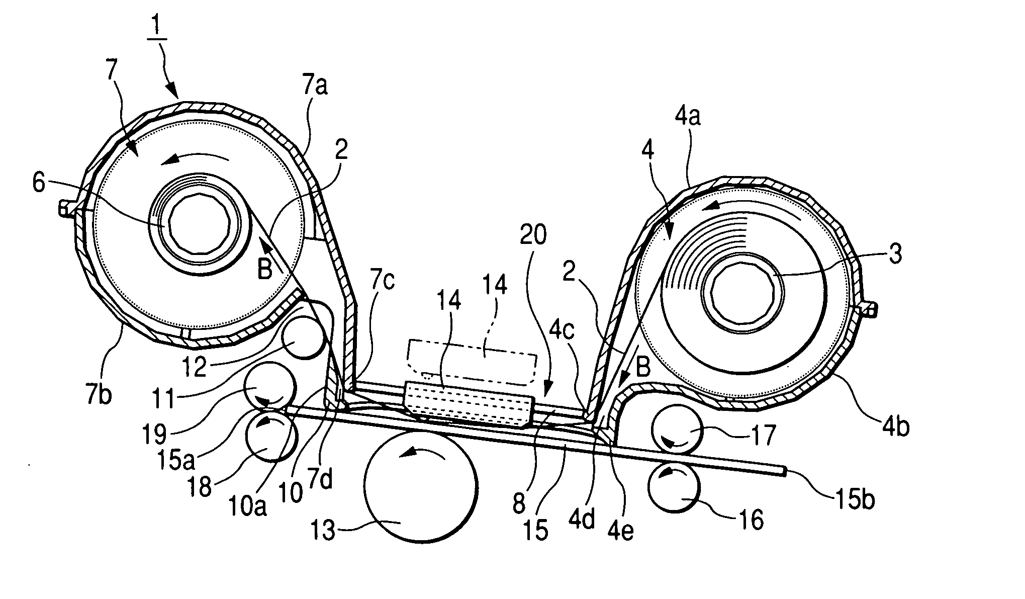
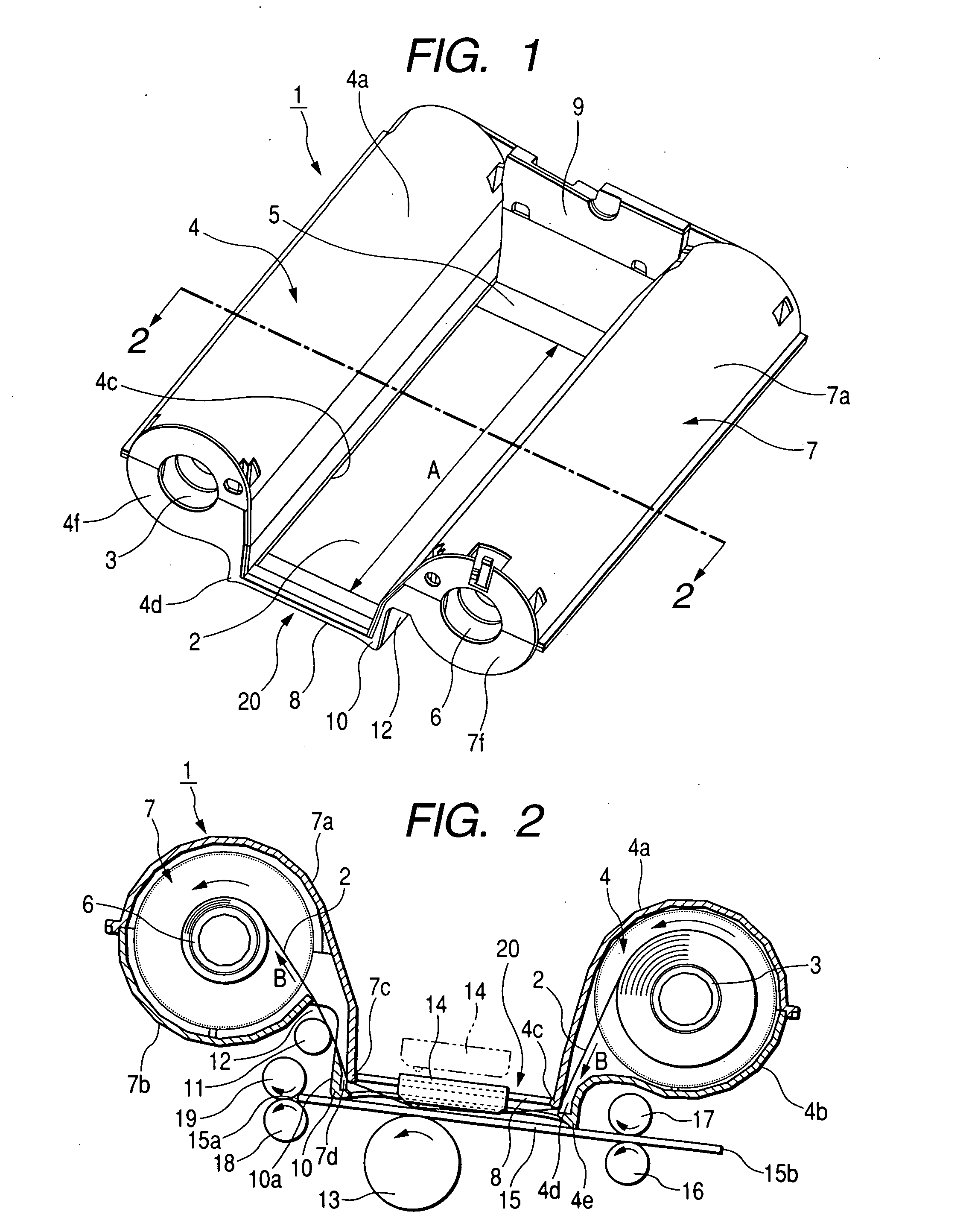
[0029] An ink ribbon cassette will be described with reference to the drawings. FIG. 1 is a perspective view of an ink ribbon cassette according to the invention, and FIG. 2 is a cross-sectional view of the ink ribbon cassette taken along line 2-2 of FIG. 1 when the ink ribbon cassette is mounted in a printer body.

[0030] The ink ribbon cassette 1 of a preferred embodiment is made of a resin material, and is provided with a first ribbon-receiving part 4 that receives a feeding reel 3 therein as shown in FIGS. 1 and 2. An unused ink ribbon 2 having a width of A is wound on the feeding reel 3.

[0031] The first ribbon-receiving part 4 includes a first wall 4a and a second wall 4b, which extend to have a substantially circular arc cross-section and have a cavity therein. A first ribbon-sliding portion 4c, with which the ink ribbon 2 to be wound on a take-up reel 6 to be described below can come in sliding contact, is formed at the lower end of the first wall 4a.

[0032] A ribbon outlet 4...


PUM


Abstract

An ink ribbon cassette is provided. The ink ribbon cassette includes a ribbon outlet provided near a first ribbon-receiving part of an ink ribbon cassette of the invention in a head insertion opening. A ribbon winding opening is provided near a second ribbon-receiving part in the head insertion opening. A first paper guide is provided at the ribbon outlet and a second paper guide is provided at the ribbon winding opening so that a recording paper to be fed is guided by the first and second paper guides.

Description

[0001] This application claims benefit of Japanese Patent Application 2005-210998 filed on Jul. 21, 2005 which is hereby incorporated by reference. BACKGROUND [0002] 1. Field [0003] An ink ribbon cassette is provided. [0004] 2. Related Art [0005] A conventional ink ribbon cassette (not shown) is mounted in a printer body 30 of a thermal transfer printer. An unused ink ribbon 31 is wound on a feeding reel 32 shown on the left side in FIG. 3. The unused ink ribbon is drawn from the feeding reel 32 through between a thermal head 34 and a platen roller 40 to be described below, and then wound on a take-up reel 33 shown on the right side in FIG. 3. [0006] The thermal head 34, which draws the ink ribbon 31 wound on the feeding reel 32, is mounted to a bracket 35. The bracket 35 is mounted to a printer body 30 with a spring 36 interposed therebetween so that the thermal head can move up and down. [0007] The thermal head 34 is disposed between a first and second feed rollers 38 and 39, whic...

Claims


Application Information

Patent Timeline
Patent Type & Authority Applications(United States)
IPC IPC(8): B41J17/32
CPCB41J11/0005B41J17/32B41J11/36
Inventor MARUYAMA, TAKAHITOABE, YOSHIBUMIMOTOKI, ZENKO
Owner ALPS ALPINE CO LTD
Why Eureka
Try Eureka