
Control system

a control system and control system technology, applied in transmission systems, tyre measurement, indirect connection of subscribers, etc., can solve the problems of inevitability of battery failure, continuing problems of users, and generating problems for users of control systems

Active Publication Date: 2007-01-18
HARMAN BECKER AUTOMOTIVE SYST
View PDF14 Cites 17 Cited by
  • Summary
  • Abstract
  • Description
  • Claims
  • Application Information

AI Technical Summary

Benefits of technology

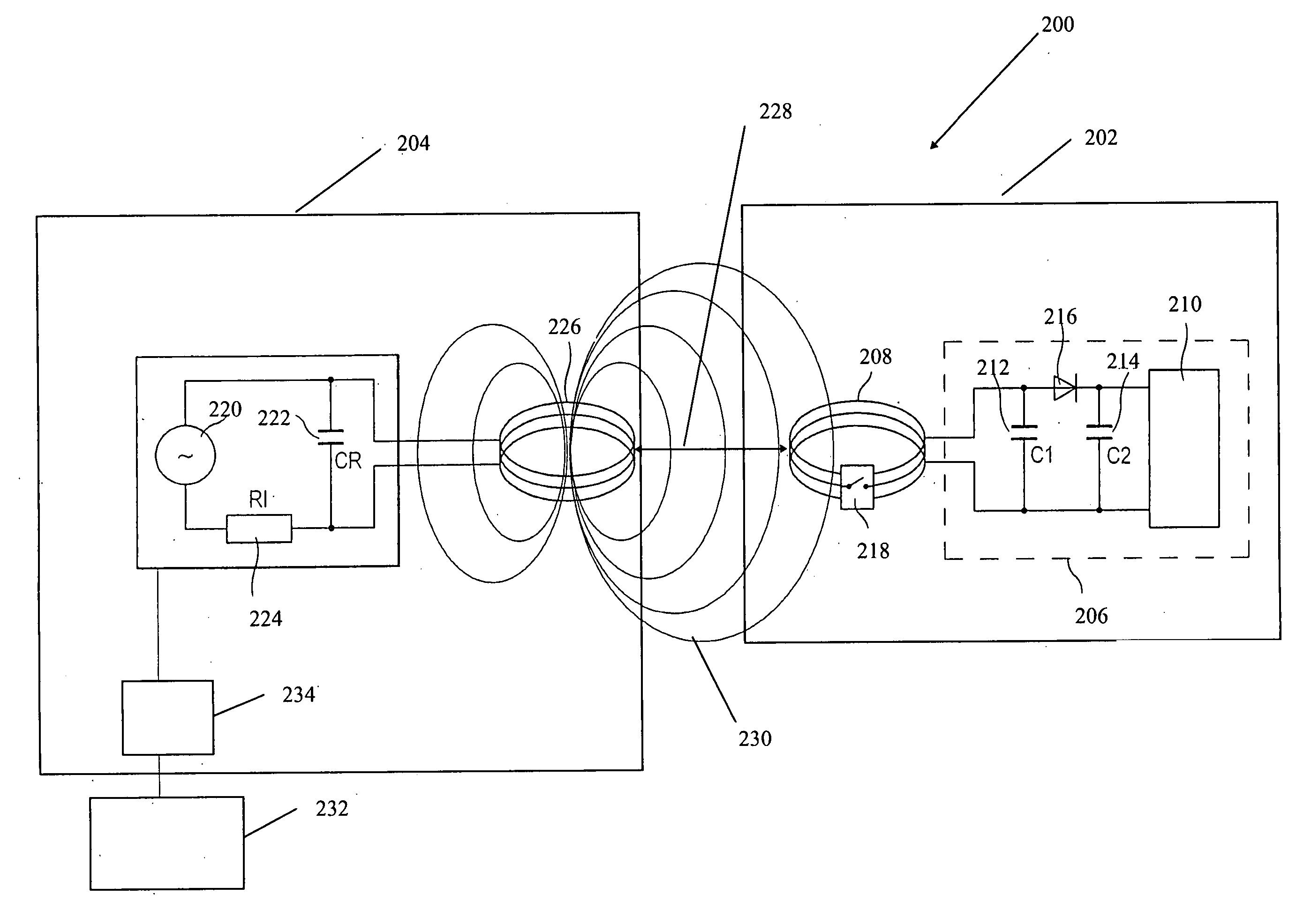
[0011] A control system for controlling an electronic device is provided. The control system may include a control apparatus and a processing device. The processing device serves to receive control signals from the control apparatus and transmits the received control signal to the electronic device. The control apparatus, which may be in the form of a remote control device, may include a transponder and a coupling unit. The transponder may be configured to receive an activation signal from the processing device and transmit a control signal to processing device. The coupling unit may be configured to enable and disable transmission of the control signal.

Problems solved by technology

Despite the many advances that have been made in design of control system for electronic systems, such control systems generate continuing problems for users.
As an example, such apparatus configured as controllers for vehicular electronic systems may give rise to problems for vehicle drivers.
The battery weight, the inevitability of battery failure, and the inconvenience of obtaining and installing a replacement battery, are annoyances to the driver.
Fabrication of such speech recognition units may represent a significant addition to the manufacturing cost and design complexity of such a control system for electronic devices.
Fallibility and inaccuracy in such speech recognition in the case of an on-board vehicular system may render difficult the precise control of various functions of a vehicular electronic device while a vehicle is being driven.
As a result, electronic device operation may either not be accurately fulfilled, or not fulfilled at all as the driver attends to driving.
Difficulties in achieving recognition of the driver's spoken commands to the speech recognition unit may detract from the driver's attention to driving the vehicle.
Undue driver preoccupation with these problems in the operation of the electronic device may thus compromise driving safety including the driver's attention to surrounding traffic situations.

Method used


Image

  • Control system
  • Control system
  • Control system

Examples


Embodiment Construction

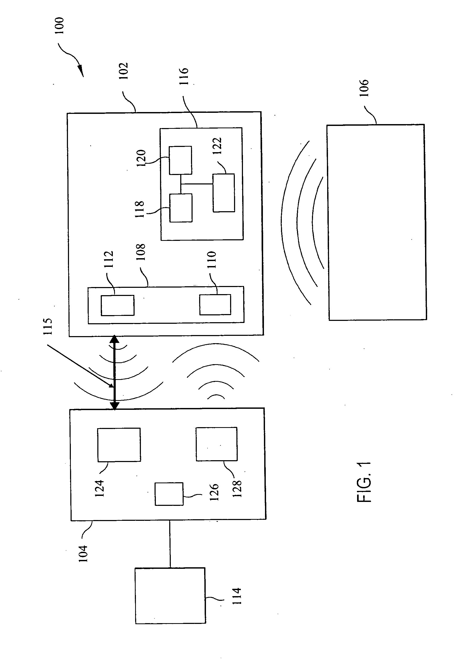
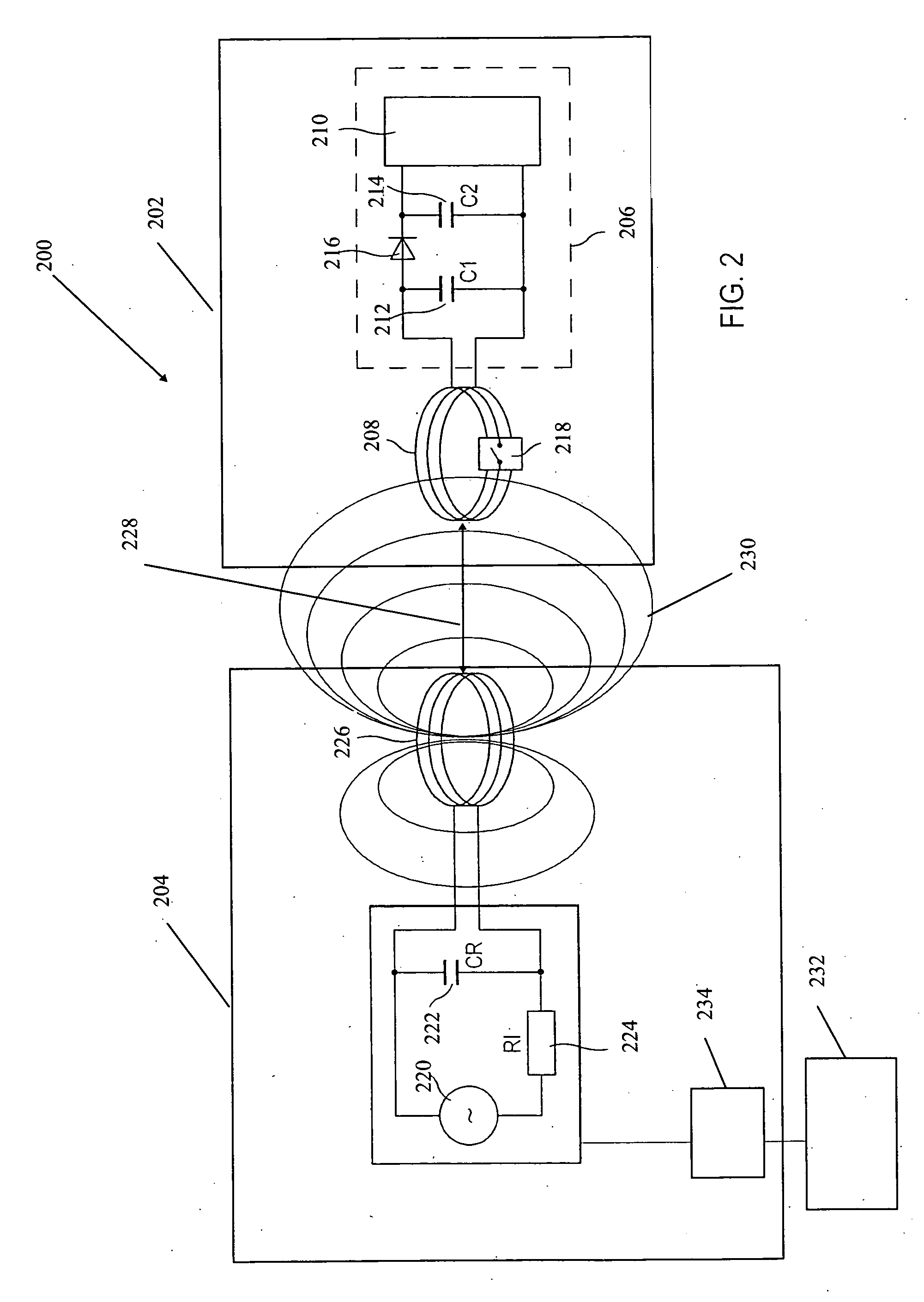
[0020]FIGS. 1-5 illustrate examples of a control system and an example method of operation of the control system. As further illustrated below, the control system may include a transponder having a signal transmission unit, for transmission of a control signal to a remote electronic device. While the control system of the invention is described as a control system for controlling a vehicular electronic system, such as a navigation system, it is understood that such control system as disclosed throughout this specification may be configured for control of non-vehicular electronic systems. At the same time, it is further understood that the control system disclosed in this specification may be configured specifically to address problems with conventional on-board control systems for vehicles.

[0021]FIG. 1 is a schematic block diagram showing one example of an implementation of a control system 100. As illustrated in FIG. 1, the control system 100 may include a control apparatus 102, a...


PUM


Abstract

A control system is provided for controlling an electronic device. The control system includes a control apparatus and a processing device. The control apparatus includes a transponder and a coupling unit. The transponder of the control apparatus may be configured to receive an activation signal and transmit a control signal to the processing device. The coupling unit may be configured to enable and disable transmission of the control signal to the processing device. The processing device may be configured to receive the control signal and communicate the control signal to an electronic device or utilize the control signal to control the electronic device.

Description

RELATED APPLICATIONS [0001] This application claims priority of European Patent Application Ser. No. 05 010 295.3, filed May 12, 2005, titled APPARATUS AND METHOD FOR REMOTE CONTROL OF AN ELECTRONIC DEVICE, which is incorporated by reference in this application in its entirety. BACKGROUND [0002][0003] 1. Field of the Invention [0004] The present invention relates to the field of control systems. In particular, the present invention relates to a control system for controlling an electronic device mounted inside a vehicle (e.g., in the vehicle compartment), such as a built-in infotainment system. [0005] 2. Related Art [0006] Various types of electronic control devices are known, including such devices for mounting in the passenger compartments of vehicles. Some electronic control devices have been configured to control on-board vehicle sound systems and navigation systems. Electronic control devices adapted for mounting in vehicles have included buttons located in operation panels arr...

Claims


Application Information

Patent Timeline
Patent Type & Authority Applications(United States)
IPC IPC(8): G08C19/00B60R25/00
CPCB60R16/027B60R25/00B60R2325/101H04B5/0081H04B5/00H04B5/0068B60R2325/105H04B5/45H04B5/26
Inventor TIPPELT, WOLF-TORSTEN
Owner HARMAN BECKER AUTOMOTIVE SYST
Learn More