
Wireless surveillance system

Inactive Publication Date: 2007-01-18
TREX ENTERPRISES CORP
View PDF5 Cites 50 Cited by
  • Summary
  • Abstract
  • Description
  • Claims
  • Application Information

AI Technical Summary

Benefits of technology

[0020] The present invention provides a surveillance system utilizing existing street lighting equipment. In a preferred embodiment, surveillance units include a small camera and a wireless transceiver and a connector that allows the surveillance units to plug into an existing outdoor light in the place of the outdoor lights' photo cells. In this preferred embodiment communication between the lights and the cellular station is at frequencies of about 2.4 GHz and uses the 802.11b protocol that permits transmission of data at up to 11 million bits per second or

Problems solved by technology

In order to limit interference among signals, however, transmitted power of WiFi systems is limited.
However, the construction of fiber optic trunk lines is expensive (sometimes very expensive) and the design and the construction of these lines can often take many months especially if the route is over private property or produces environmental controversy.
Often the expected revenue from the potential users of a particular trunk line under consideration does not justify the cost of the fiber optic trunk line.
In conjunction with the above availability requirements, weather-related attenuation limits the useful range of wireless data transmission at all wavelengths shorter than the very long radio waves.
At the higher, millimeter-wave frequencies, (i.e., 30 GHz to 300 GHz corresponding to wavelengths of 1.0 centimeter to 1.0 millimeter) where available bandwidth is highest, rain attenuation in very bad weather limits reliable wireless link performance to distances of 1 mile or less.
There is no viable solution today for large-scale deployment of video surveillance cameras throughout a large campus or metropolitan areas or at a single facility with large numbers of entrances and exits or other areas that require surveillance.
Many thousands of facilities are potential targets of people that want to cause us harm.

Method used


Image

  • Wireless surveillance system
  • Wireless surveillance system
  • Wireless surveillance system

Examples


Embodiment Construction

Wireless Outdoor Light Surveillance System

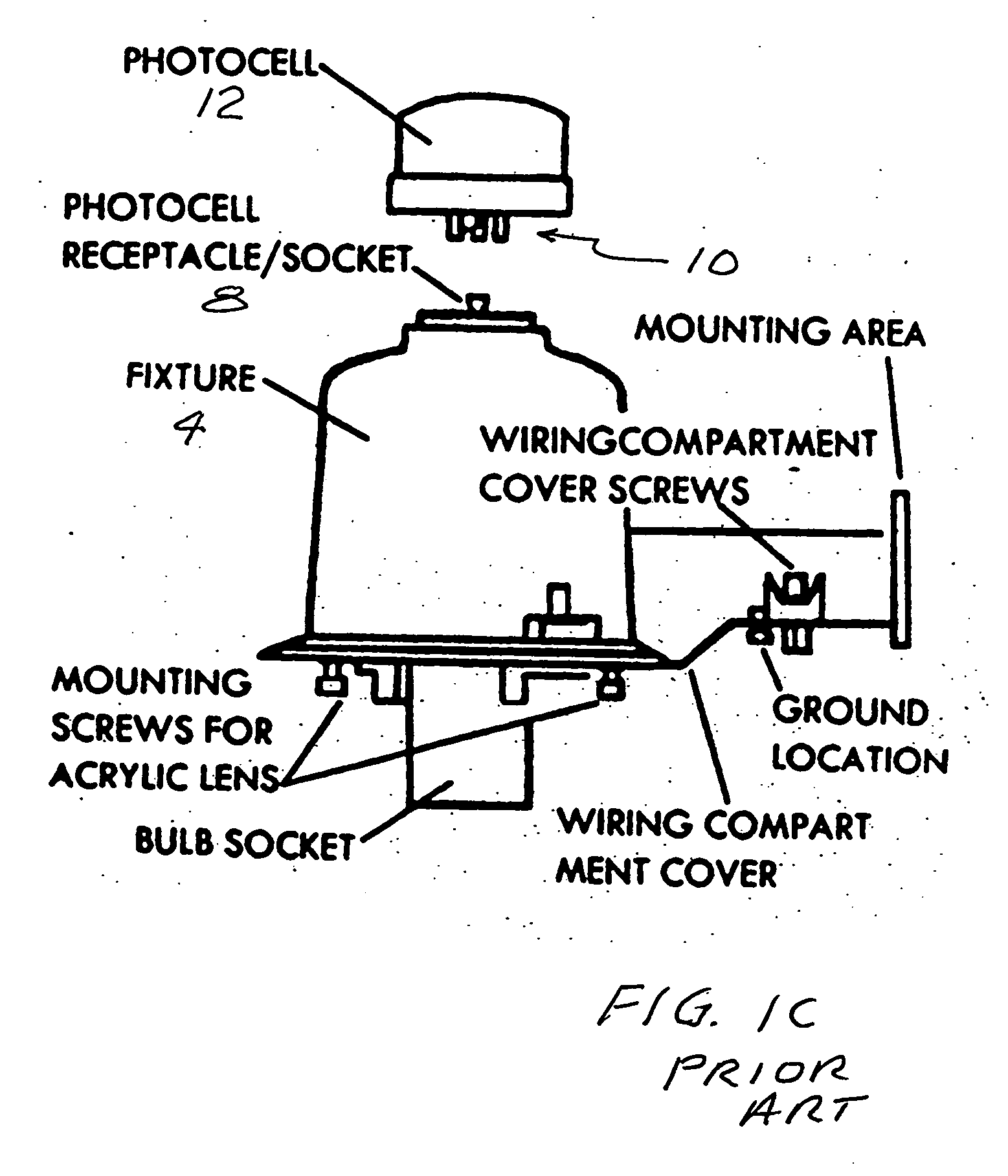
[0026]FIG. 3 is a drawing of a surveillance unit plugged into the photocell receptacle of an outdoor light. The surveillance unit includes a small digital CMOS camera 40, a motion detector 42, transceiver 44, a computer processor 46, memory unit 48, photocell 50 and control switch 52. All of these electronic components are available individually off the shelf and all of the components except the photocell and the control switch are currently being utilized in digital surveillance wireless camera units that are also currently available from suppliers such as Veo International. The unique feature of this embodiment is that it plugs into the photocell receptacle 8 of light fixture 4. The very important advantage of this feature is that a surveillance station can be set up in just a very few minutes at negligible installation cost utilizing existing street lighting, parking lot lighting and perimeter lighting. Low cost of the individual units w...


PUM


Abstract

A surveillance system utilizing existing street lighting equipment. In a preferred embodiment, surveillance units include a small camera and a wireless transceiver and a connector that allows the surveillance units to plug into an existing outdoor light in the place of the outdoor lights' photo cells. In this preferred embodiment communication between the lights and the cellular station is at frequencies of about 2.4 GHz and uses the 802.11b protocol that permits transmission of data at up to 11 million bits per second or the 802.11g protocol that permits transmission of data at up to 54 million bits per second. The cellular stations then communicates with the central monitoring station at a frequency range of 71-76 GHz and 81 to 86 GHz that permits transmission of data at about 1.0 billion bits per second. In an example system, with 1,000 surveillance cameras (each camera unit plugged into the photocell receptacle of a street light), 100 camera units communicate with each of 10 cellular stations and the 10 cellular stations communicate with a single central monitoring station.

Description

[0001] The present invention is a continuation in part of Ser. No. 10 / 859,006 filed Jun. 2, 2004 and a continuation in part application of Ser. No. 10 / 799,255 filed Mar. 30, 2004 which is a continuation in part of Ser. No. 09 / 847,629 filed Sep. 14, 2001, now U.S. Pat. No. 6,714,800 issued Mar. 30, 2004. This application also claims the benefit of Ser. No. 60 / 666,084, filed Mar. 28, 2005 and Ser. No. 60 / 691,270 filed Jun. 15, 2008. The present invention relates to outdoor lighting and surveillance and security systems and in particular to the combination of outdoor lighting with wireless surveillance security systems.BACKGROUND OF THE INVENTION Need for Security [0002] Especially since Sep. 11, 2001 security has become big business in the United States and in most countries of the world. People and governments are concerned with the protection of locations that are terrorist targets. These include stadiums, government installations and military installations. Most terrorist targets a...

Claims


Application Information

Patent Timeline
IPC IPC(8): G08B13/00H04N7/18
CPCG08B13/19634G08B13/19658H04N7/181G08B13/19695G08B13/1966
Inventor TANG, KENNETH Y.BREES, LANCECHEDESTER, RICHARD
Owner TREX ENTERPRISES CORP
Learn More