
Head-protecting airbag apparatus

Inactive Publication Date: 2007-01-18
TOYODA GOSEI CO LTD
View PDF8 Cites 12 Cited by
  • Summary
  • Abstract
  • Description
  • Claims
  • Application Information

AI Technical Summary

Benefits of technology

[0014] the dividing recess, in the event that the third shielding portion engages the folded third-row seat during the course of airbag deployment, separates a lower edge of a region between the second shielding portion and the third shielding portion, so that the second shielding portion is not hindered from smooth development.
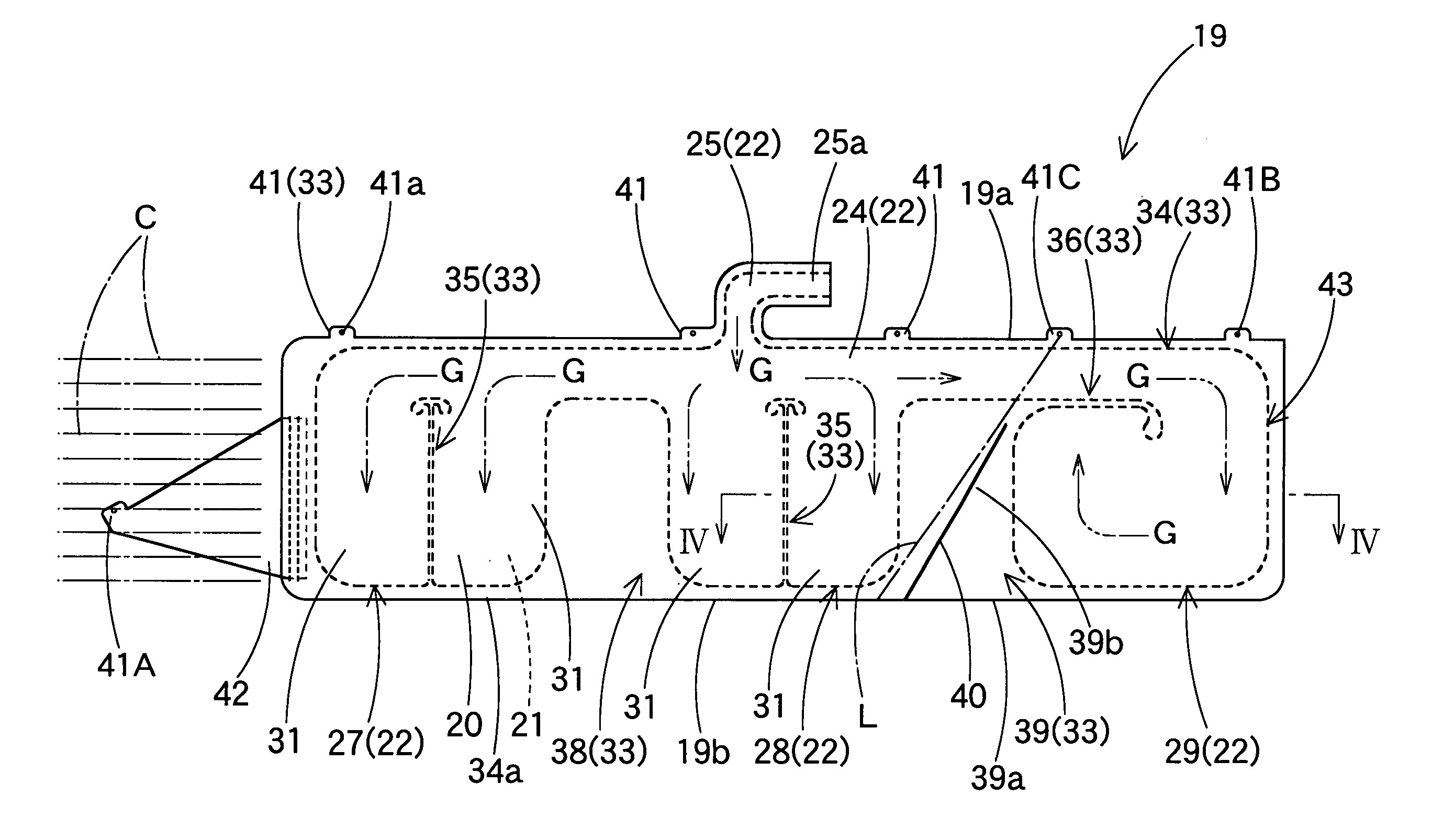
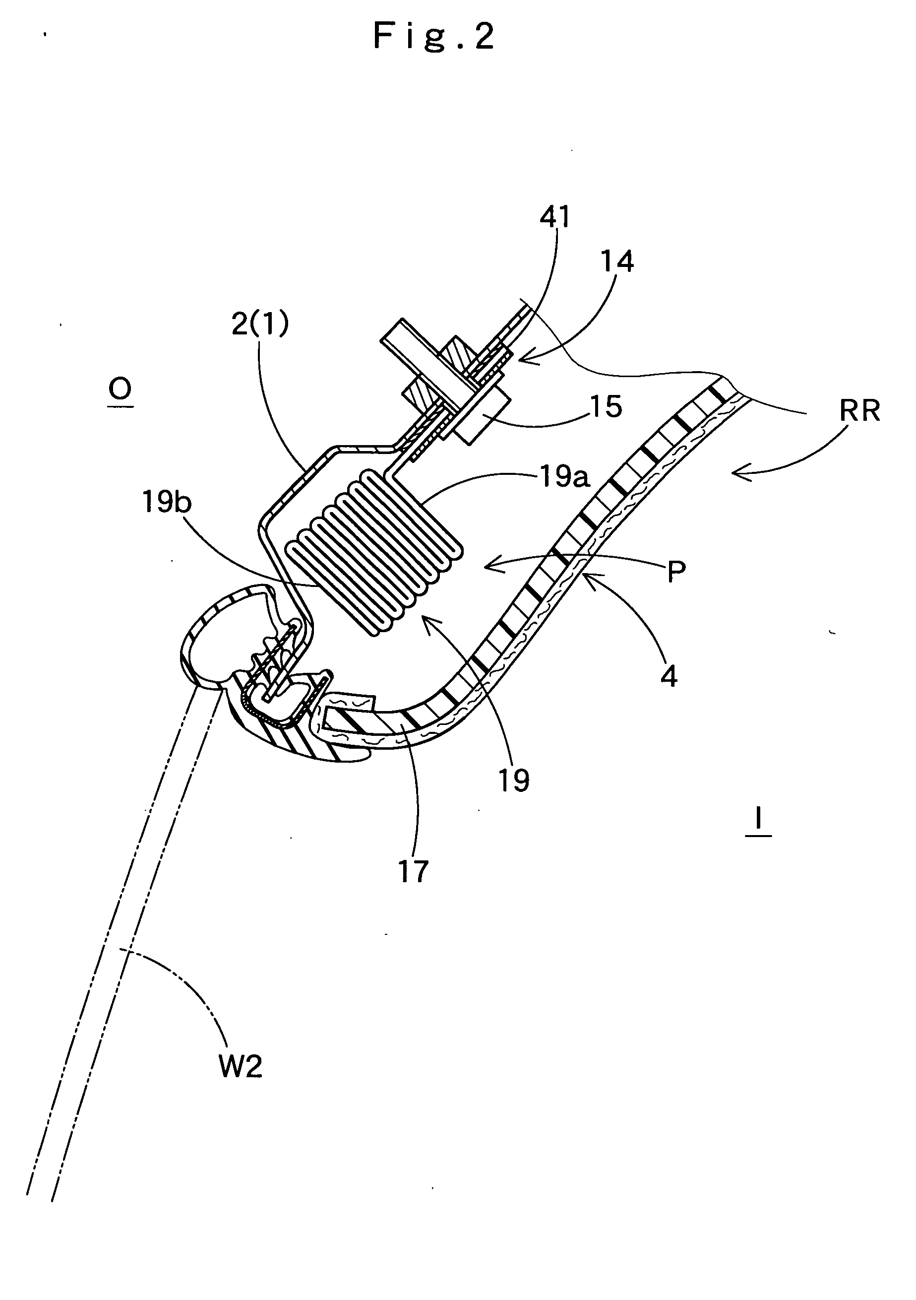
[0015] In the airbag apparatus of the present invention, the airbag is provided with the dividing recess extending upward from the lower edge, in an area of the non-admissive portion located between the second shielding portion and the third shielding portion. In the event that the third shielding portion engages the third-row seat during the course of airbag deployment when the third-row seat is not occupied by a passenger and therefore folded or put away as to stand proximate to the inner side of the third-row window, the recess separates the lower edge region between the second shielding portion and the third shielding portion, thereby the second shielding portion is not hindered from smooth development. Accordingly,the first and second shielding portions are capable of developing and inflating smoothly for covering the interior side of the windows located at the sides of the first and second-row seats.
[0016] Therefore, in the head-protecting airbag apparatus of the present invention, the shielding portions of the airbag for covering the interior side of the first- and second-row windows are capable of developing and inflating smoothly in the,event of absence of a passenger in the third-row seat, although the airbag includes three inflatable shielding portions for covering the interior side of the windows.
[0018] In the above-described airbag apparatus, the dividing recess may be provided at its leading end with a punched out portion recessed in a generally arcuate shape. The punched out portion will serve to relieve a stress concentration that would otherwise be created on the leading end of the dividing recess in the event that the third shielding portion engages the third-row seat folded and located proximate the interior side of the third-row window during airbag deployment.
[0021] With this arrangement, the breakable portion does not break unless the third shielding portion hits the third-row seat. Hence the airbag completes inflation with the region between the second shielding portion and the third shielding portion intact or unseparated. Therefore, the airbag has a large coverage area for covering the interior side of the window and its surroundings including a pillar. When the third shielding portion engages the folded third-row seat, the breakable portion breaks, and separates, the lower edge region between the second shielding portion and the third shielding portion. Hence the third shielding portion does not affect the development of the second shielding portion, but allows the first and second shielding portions to deploy smoothly and cover the interior side of the windows located at the sides of the first and second-row seats.

Problems solved by technology

When the conventional airbag having three shielding portions deploys while the third-row seat is folded up, however, if the third-row seat is so put away as to stand proximate to the interior side of window, the third shielding portion adapted to cover the interior side of a window located at the side of the third-row seat is likely to engage the folded seat, and therefore be hindered from smooth development.
Moreover, this may affect the first and second shielding portions deployable to cover the side of the first and second row seats which are occupied by vehicle occupants, and result in hindering the smooth deployment of the first and second shielding portions.

Method used


Image

  • Head-protecting airbag apparatus
  • Head-protecting airbag apparatus
  • Head-protecting airbag apparatus

Examples


Embodiment Construction

[0039] Preferred embodiments of the present invention are described below with reference to the accompanying drawings. However, the invention is not limited to the embodiments disclosed herein. All modifications within the appended claims and equivalents relative thereto are intended to be encompassed in the scope of the claims.

[0040]FIG. 1 illustrates a head-protecting airbag apparatus M embodying the present invention. The airbag apparatus M is mountable on a vehicle V with three rows of seats, S1, S2, S3 which seats are arranged one behind another in the vehicle's longitudinal direction. The airbag apparatus M is mounted on a front pillar FP and a roof side rail RR along the upper edge of windows or side windows W1, W2 and W3 through the region above a rear pillar RP. When not in service, the third-row seat S3 is so folded or put away as to stand proximate to the interior side of window W3, as indicated by double-dotted lines in FIG. 6.

[0041] The head-protecting airbag apparatu...


PUM


Abstract

The head-protecting airbag apparatus according to the present invention is mounted on a vehicle whose third-row seat is so put away as to stand proximate to the inner side of a window. The airbag has three shielding portions, and includes a dividing recess between the third shielding portion and second shielding portion. In the event that the third shielding portion engages the folded seat during the course of airbag deployment, the dividing recess separates the lower edge of a region between the second shielding portion and the third shielding portion, so that the second shielding portion is not hindered from smooth development.

Description

[0001] The present application claims priority from Japanese Patent Application No. 2005-205879 of Kino et al., filed on Jul. 14, 2005, the disclosure of which is hereby incorporated into the present application by reference. BACKGROUND OF THE INVENTION [0002] 1. Field of the Invention [0003] The present invention relates to a head-protecting airbag apparatus mounted on a vehicle having three rows of seats. [0004] 2. Description of Related Art [0005] In the prior art, Japanese Patent Laid-Open No. 2002-200959 is illustrative of a head-protecting airbag apparatus mounted on a vehicle having three rows of seats. This apparatus includes an airbag which is folded and housed in the upper edge of windows inside the vehicle, and is deployable to cover the interior side of windows when fed with inflation gas from an inflator. In the conventional head-protecting airbag apparatus, the airbag includes three shielding portions inflatable with inflation gas so as to cover the interior side of th...

Claims


Application Information

Patent Timeline
IPC IPC(8): B60R21/213B60R21/233B60R21/20B60R21/232
CPCB60R21/213B60R21/232B60R2021/23386B60R2021/23316B60R21/2338
Inventor KINO, MASSAOHOTTA, NAOKIOCHIAI, YASUOMASUDA, YASUSHI
Owner TOYODA GOSEI CO LTD
Learn More