
Espresso coffee maker having an espresso brew unit

a coffee maker and espresso technology, applied in the field of espresso coffee makers, can solve the problems of scalding danger and loss of espresso later freshly brewed, and achieve the effect of compact and robust structur

Active Publication Date: 2007-01-18
EUGSTER FRISMAG
View PDF2 Cites 35 Cited by
  • Summary
  • Abstract
  • Description
  • Claims
  • Application Information

AI Technical Summary

Benefits of technology

The present invention relates to an improved espresso coffee maker that solves the problem of uncontrolled coffee brew or espresso flow after the brewing process is finished. The invention provides a solution by introducing a return-flow suction unit that automatically activates when the brewing process is finished. The suction unit prevents coffee residue from remaining in the coffee outflow duct and requires no additional servicing. The invention also includes a brew chamber element that can be moved vertically to disconnect from the top ram and allow for the complete opening of the brew chamber for cleaning and maintenance. The coupling elements between the brew chamber element and the suction piston are reliable and wear-resistant. Overall, the invention provides a more efficient and reliable espresso coffee maker.

Problems solved by technology

This residual coffee will either leave the coffee outflow as a slow leakage even if there is no receptacle under it, or the residual coffee will remain in the coffee outflow duct until a further brewing process is initiated thus causing a quality loss of the espresso later freshly brewed.
The slow leakage from the coffee outflow can soil its surroundings, and in case of careless or awkward handling, even the danger of scalding cannot be completely ruled out.

Method used


Image

  • Espresso coffee maker having an espresso brew unit
  • Espresso coffee maker having an espresso brew unit
  • Espresso coffee maker having an espresso brew unit

Examples


second embodiment

[0035] the return-flow suction unit 21a according to FIG. 4 includes, instead of the suction cylinder 22 and its coupling elements, in addition to espresso brew unit 1a, only one valve 32 including a spring-loaded ball 33 which, in the closed position shown in FIG. 4, closes an upper valve seat not designated when there is no under pressure in brew chamber 2. The valve 32 will also take this closure position in particular when espresso is brewed by feeding brewing water from the brewing water feeder nozzle 12 over the brewing water distribution chamber 13 into the brew chamber and, when the brew chamber has attained a predetermined internal pressure, flows via the crema valve 15 into the coffee outflow duct 18.

[0036] When in order to finish the brewing process the brewing water inflow to the brew chamber 2 has been stopped and when the brew chamber cylinder 3 moved downwardly generates, by the bottom ram 4, an underpressure in the brew chamber 2, the valve 32 is opened contrary to t...

third embodiment

[0038] espresso brew unit 1b according to FIG. 5 including the return-flow suction unit 21b differs from espresso brew unit 1a including the return-flow suction unit 21a only by a different valve 34 in addition to the crema valve 15. The additional valve 34 includes a ball 35 that is not spring-loaded. Normally, ball 35 lies simply by action of gravity on a lower fluid-conductive valve seat 36 which is in permanent connection with the brew chamber 2.

[0039] An exemplary form of fluid-conductive valve seat 36 is shown in a plan view according to FIG. 6. It consists here essentially of three non-designated support arms extending into an opening and on which the ball 35 is disposed as long as it is not pushed by the brew chamber internal pressure against an upper, non-designated, valve seat and sealing that valve seat against suction duct 28 and coffee outflow duct 18. Sealing is already obtained at a low internal pressure in the brew chamber before the crema valve is opened by the pres...


PUM


Abstract

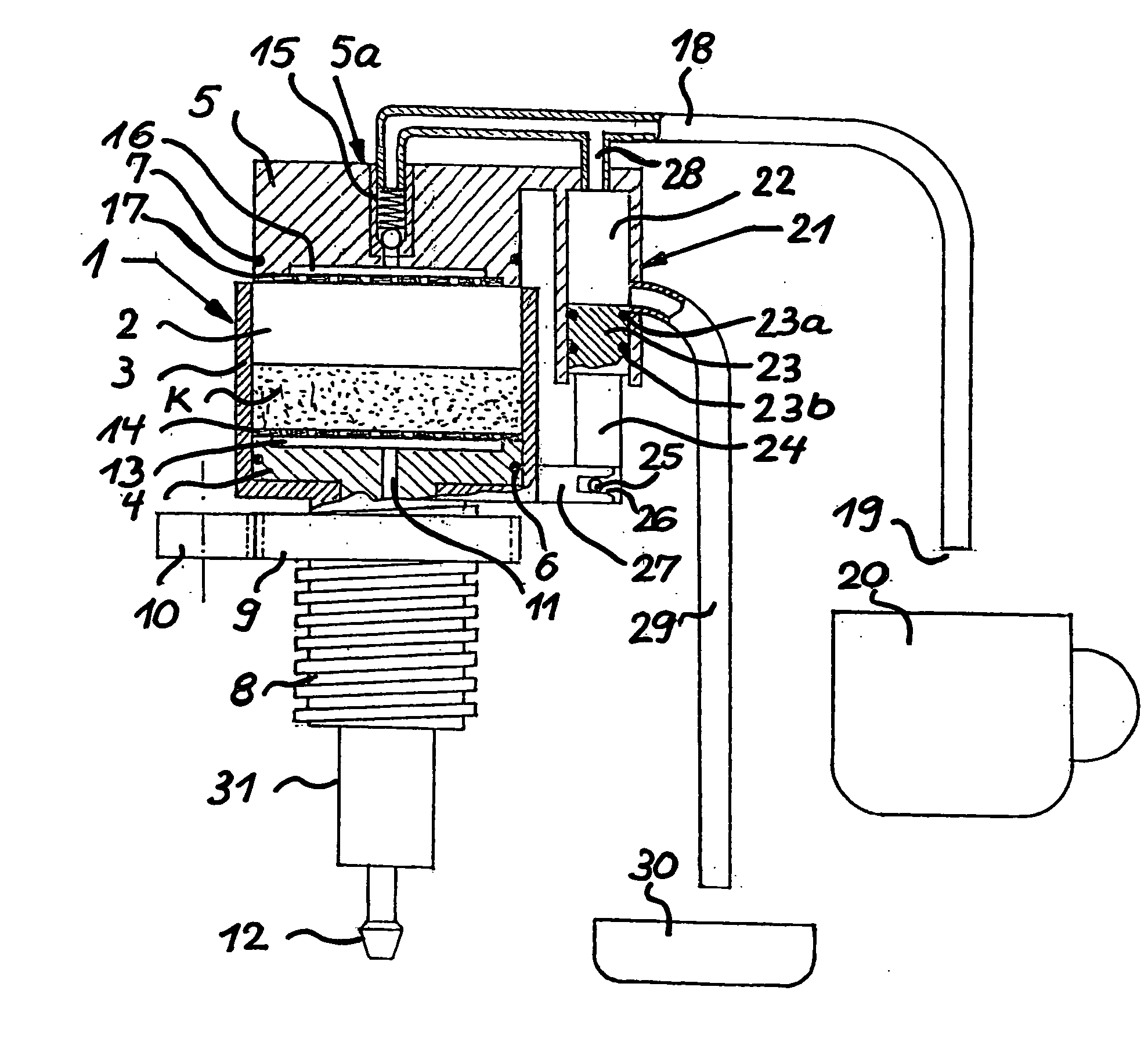
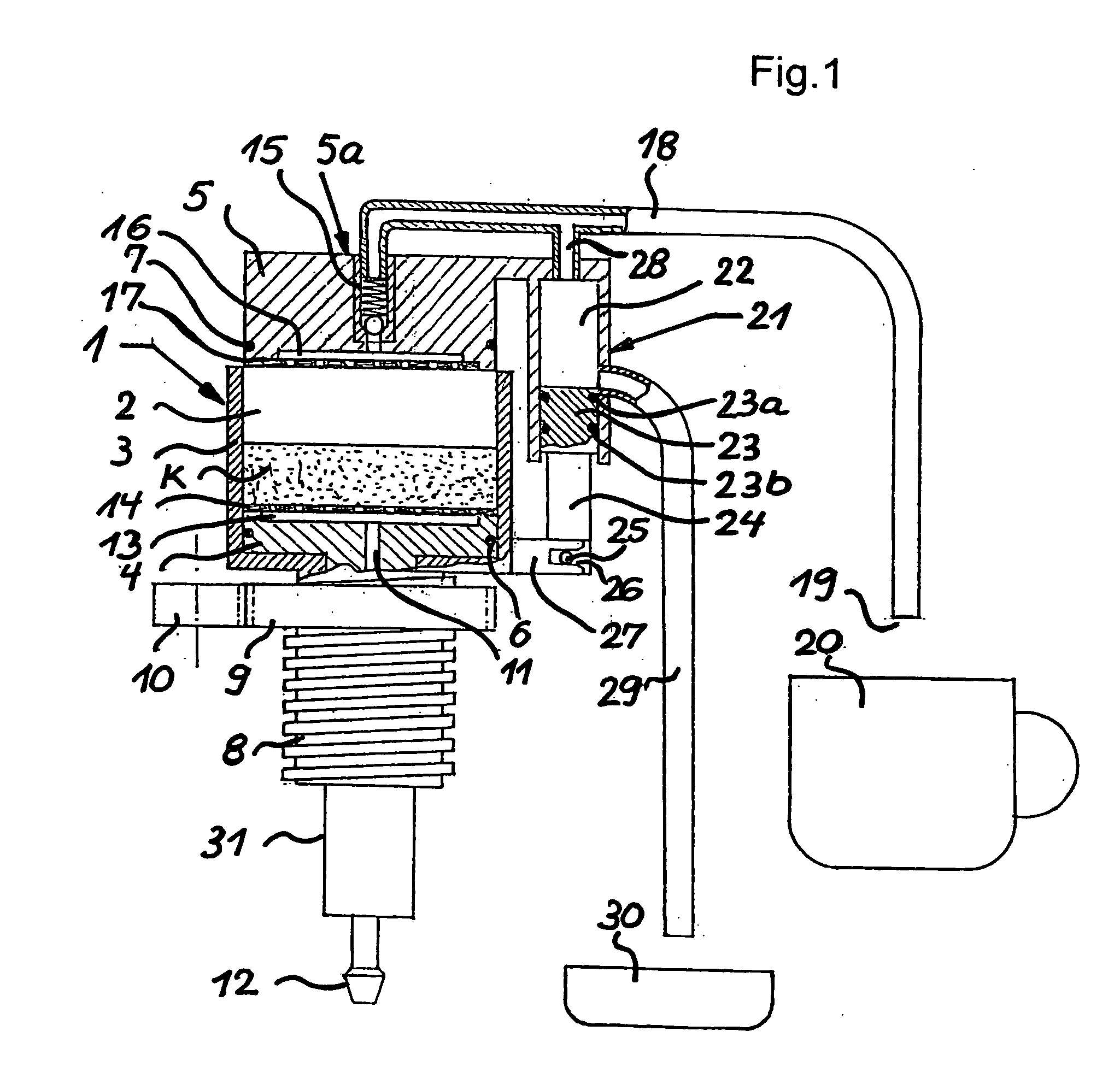
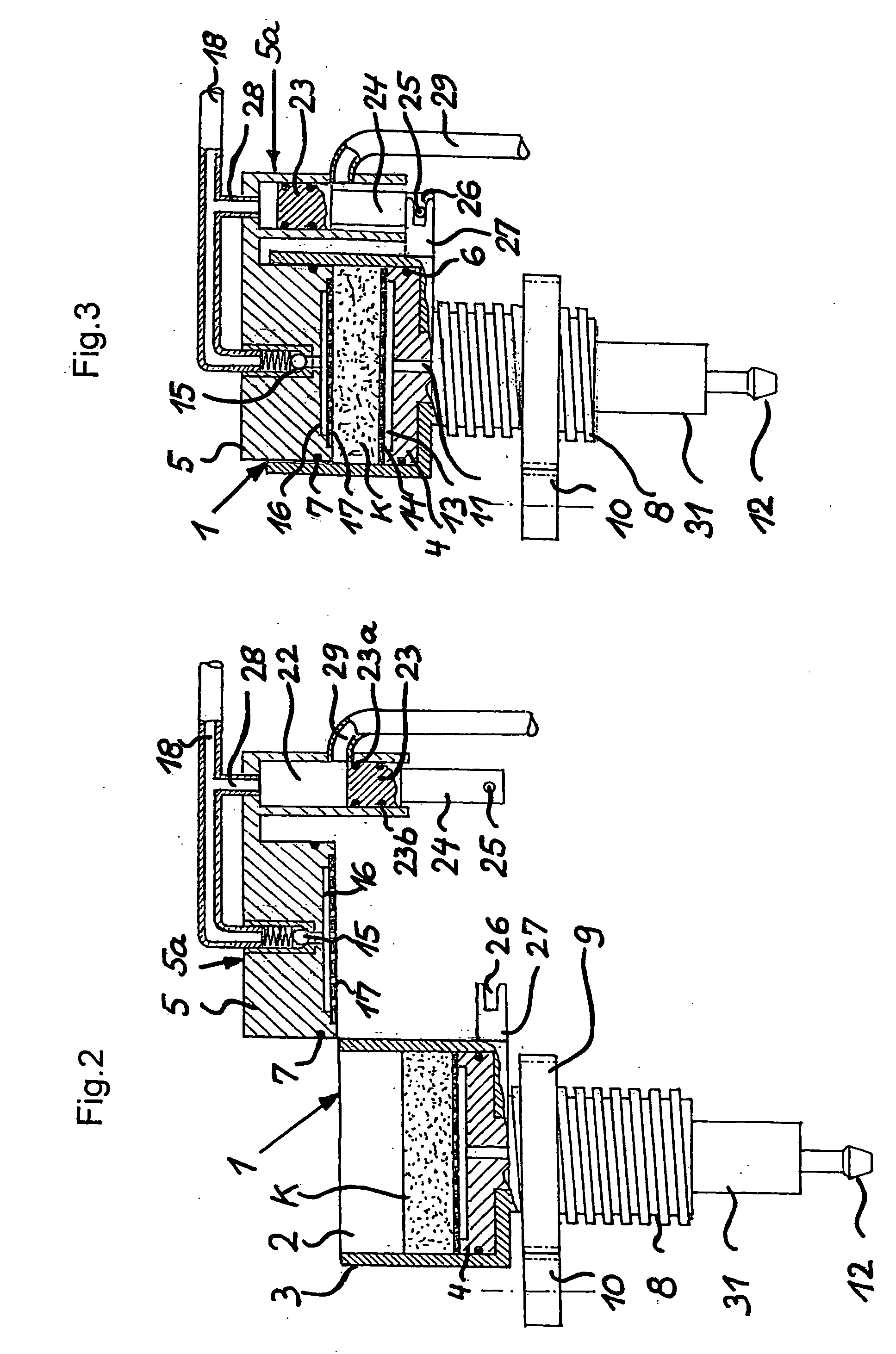
In an espresso coffee maker having an espresso brew unit (1) and a coffee outflow duct (18) in fluid-conductive connection with the espresso brew unit via a crema valve (15) and having an end sided coffee outflow (19), no brewed residual coffee should remain in the coffee outflow duct nor leak out, for instance as leakage, through the coffee outflow. In order to avoid this, a return-flow suction unit (21), which is preferably independent except for a drive means, is in fluid-conductive connection with the coffee outflow duct (18) between crema valve (15) and coffee outflow (19), which is automatically activated when a brewing process is finished.

Description

BACKGROUND OF THE INVENTION [0001] 1. Field of the Invention [0002] The present invention relates to an espresso coffee maker having an espresso brew unit and a coffee outflow duct in fluid-conductive connection with the espresso brew unit via a crema valve and having an end sided coffee outflow. [0003] 2. Description of the Related Art [0004] In such prior art espresso coffee makers, when finishing the brewing process and hence closing the crema valve, residual coffee will remain in the coffee outflow duct which connects, as a hose and / or tubular duct, the espresso brew unit with the coffee outflow. This residual coffee will either leave the coffee outflow as a slow leakage even if there is no receptacle under it, or the residual coffee will remain in the coffee outflow duct until a further brewing process is initiated thus causing a quality loss of the espresso later freshly brewed. The slow leakage from the coffee outflow can soil its surroundings, and in case of careless or awkw...

Claims


Application Information

Patent Timeline
Patent Type & Authority Applications(United States)
IPC IPC(8): A47J31/44A47J31/24A47J31/36A47J31/40A47J31/46
CPCA47J31/3609A47J31/46A47J31/4496A47J31/3614A47J31/461
Inventor OEHNINGER, MAX
Owner EUGSTER FRISMAG
Learn More