
Vehicle suspension system, particularly for road and off-road vehicles

a suspension system and vehicle technology, applied in the direction of suspensions, interconnection systems, suspensions, etc., can solve the problems of high price, less durable and reliable than the suspension fitted with steel springs, and substantially inferior suspension damping characteristics to those of pneumatic and hydro-pneumatic suspensions

Inactive Publication Date: 2005-02-08
OLEDZKI JULIAN WIESLAW
View PDF10 Cites 6 Cited by
  • Summary
  • Abstract
  • Description
  • Claims
  • Application Information

AI Technical Summary

Benefits of technology

"The present invention provides a universal vehicle suspension system that is extraordinarily compact and robust in structure, and has a progressive suspension rate that is derived from the kinetics of a flat four-link mechanism. The suspension system features a non-linear differentiable damping characteristic that can be freely modeled according to specific requirements, and is self-sufficient in the sense that no additional elements are needed to hold the vehicle's road wheel. The suspension system is simple and inexpensive to manufacture, and provides the possibility of a relative position between the road wheel and the spring during overhauls. The suspension system is also easy to assemble in existing vehicles and improves shock absorption within the entire range of dynamic loads and vehicle weight variations."

Problems solved by technology

Vehicle suspensions fitted with steel springs are compact, robust, durable and reliable, but they usually feature constant suspension rate and linear damping characteristic inherited from the linear characteristic of the steel spring they use, which is considerably inferior to that of the pneumatic suspension.
However in both these cases the suspension damping characteristic still remains substantially inferior to that of the pneumatic and hydro-pneumatic ones.
Pneumatic and hydro-pneumatic vehicle suspensions feature favorable differentiable progressive damping characteristic, but they are expensive and much less durable and reliable than suspensions fitted with steel springs.
Moreover, a major disadvantage of both the suspensions in question is that their damping characteristic is determined by the thermodynamic parameters of the gas (air or nitrogen) they utilize (namely the adiabatic exponential), and therefore cannot be freely adjusted to specific requirements.
Moreover, the damping characteristic of such suspensions is still far from optimal.
A common feature of all commonly used vehicle suspension systems is that their characteristic is determined in great part by the characteristic of the spring being used, and therefore is hard to make optimum.
Consequently, these suspensions are excessively complicated, of questionable, if not doubtful, durability and reliability, unable to cope with large loads, and means for adjusting damping characteristic of them are completely unsatisfactory.
Again this suspension is far from being satisfactory for at least the following reasons: For the first, to adjust (increase) the torsion bar spring rate to increasing vehicle weight, the length of said torsion bar is being decreased, which diminishes the spring capability of accumulating potential energy.
For the third, means for adjusting suspension rate are not capable of varying the spring rate continuously, and therefore the damping characteristic of the suspension is not differentiable and far from optimal.

Method used


Image

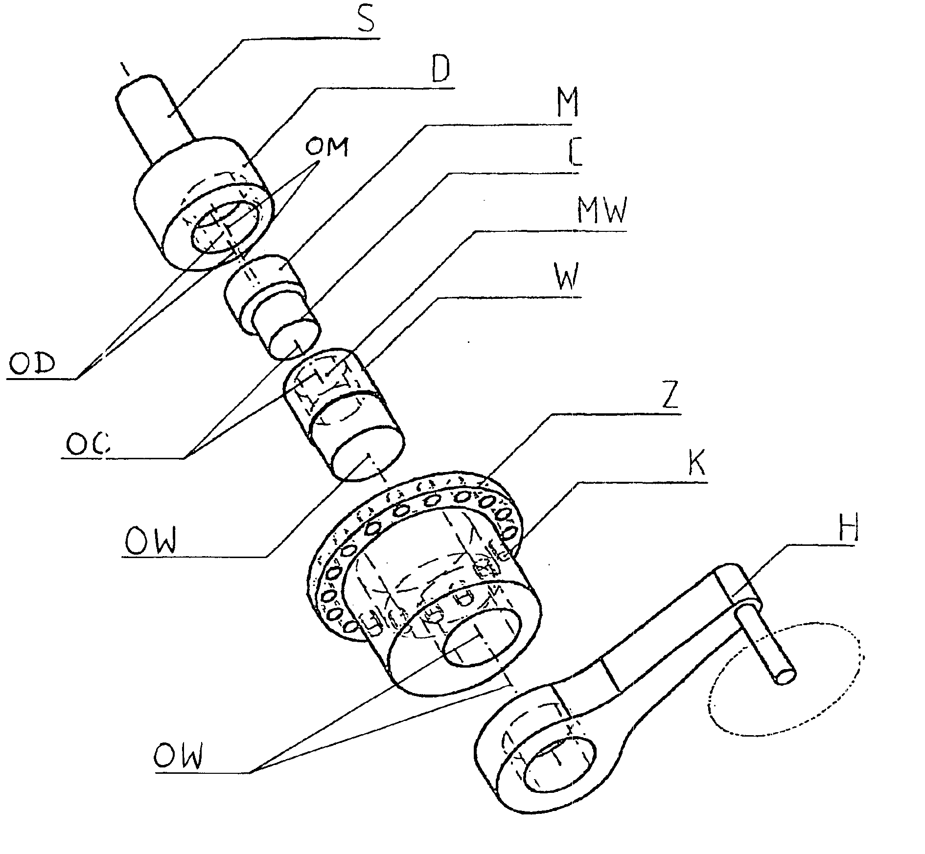
  • Vehicle suspension system, particularly for road and off-road vehicles
  • Vehicle suspension system, particularly for road and off-road vehicles
  • Vehicle suspension system, particularly for road and off-road vehicles

Examples


example 2

Referring to FIGS. 4-6 there is shown another suspension unit fitted with a torsion bar in accordance with the present invention.

The suspension mechanism (FIGS. 5 and 6) comprises a shaft (W) fitted with an eccentric (WM), said eccentric (WM) being pivoted in an eccentric bore chamber (MW) of an intermediate eccentric (M), whereas the eccentric (M) pivots inside of an eccentric bore chamber (DM) in a disc (D). The shaft (W) and the disc (D) pivot directly in a body (K) in their respective circular bore chambers (KW) and (KD).

One end of a torsion bar (S) is coupled rigidly with the shaft (W) and the other end of torsion bar (S) is anchored in a vehicle frame (F). A trailing arm (H) is coupled with the disc (D). The whole suspension unit is fixed to the vehicle frame (F) with the help of a flange (Z) at the body (K).

In this arrangement the axis (OW) of rotation of the shaft (W) relative the body (K) (which overlaps the symmetry axis of the circular bore chamber (KW)), the axis (OD) of...

example 3

Referring to FIGS. 7-9, there is shown a suspension system fitted with a coil spring and a trailing arm in accordance with the present invention.

The suspension mechanism (FIGS. 8 and 9) comprises a shaft (W) fitted with an eccentric (WM), wherein the eccentric (WM) pivots in an eccentric circular bore chamber (MW) in an intermediate eccentric (M), and the intermediate eccentric (M) pivots inside of an eccentric circular bore chamber (DM) in the disc (D). The disc (D) pivots in a circular bore chamber (KD) placed directly in a body (K), and the body (K) is coupled rotationally with the shaft (W) through a circular bore chamber (KW).

An arm (H) is fastened to the intermediate eccentric (M). The body (K) is fitted with a bracket (KS), on which one end of a coil spring (S) is being supported, the other end of which rests on a vehicle frame (F). The whole suspension unit is fastened to the vehicle frame (F) with the help of a flange (Z) at the shaft (W).

In this arrangement the axis (OW) o...

example 4

Referring to FIGS. 10, 11, there is shown a vehicle suspension unit, which is just a variant of the unit shown in FIGS. 7-9, in which the spring is compressed by two different links of the suspension mechanism (through brackets fastened to the suspension mechanism's body and a road wheel arm, which in turn is fastened to the mechanism shaft).

Thus the suspension mechanism (FIG. 11, see also FIGS. 8, 9) comprises a shaft (W) fitted with an eccentric (WM), wherein the eccentric (WM) pivots in an eccentric circular bore chamber (MW) in an intermediate eccentric (M), and the intermediate eccentric (M) pivots inside an eccentric circular bore chamber (DM) in the disc (D). The disc (D) pivots in a circular bore chamber (KD) (FIG. 8) placed directly in a body (K), which in turn is coupled rotationally with the shaft (W) through a circular bore chamber (KW).

A trailing arm (H), fitted with a bracket (HS), is coupled rigidly with the intermediate eccentric (M). The body (K) is fitted with a br...


PUM


Abstract

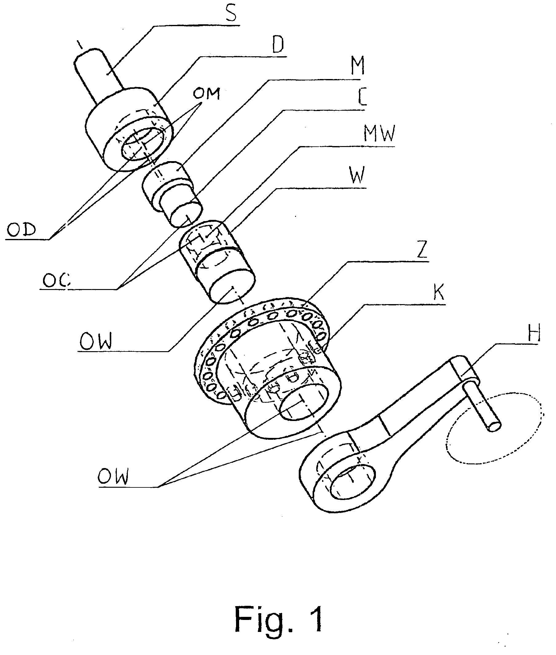
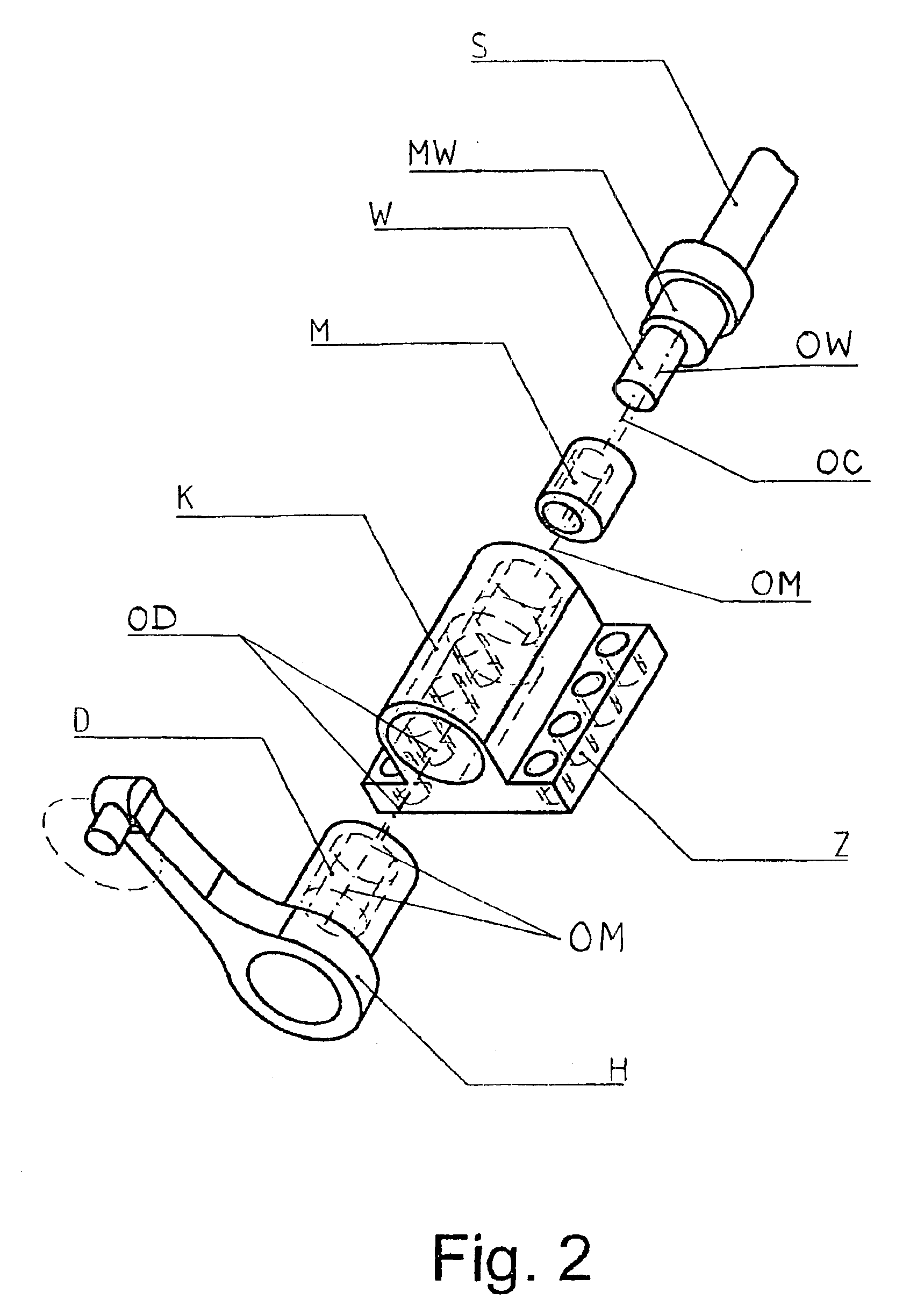
This invention relates to vehicle suspension, destined particularly for heavy road and off-road vehicles and first of all for those whose weight and dynamical loads vary within a broad range during the operating process, and is particularly concerned with improvements to the suspension characteristic, i.e. suspension stiffness as a function of axle deflection. The suspension according to the invention is distinguished for the fact that it comprises at least one flat or spatial four-link mechanism (K), (M), (W) and (D) three kinematic pairs of which are rotational ones and one is a rotational or a sliding one, wherein two links of said mechanism are made in the form of eccentric and one link is made in the form of eccentric or slider, wherein one of the links of said mechanism is coupled with vehicle's wheel, another link of the mechanism is coupled with a spring (S), and the whole mechanism is mounted to the vehicle frame using yet another of its links, to get a non-linear differentiable dependence of the suspension stiffness on the vehicle wheel deflection.

Description

TECHNICAL FIELD OF THE INVENTIONThe present invention relates to a vehicle suspension system, particularly for road and off-road vehicles such as trailers and semi-trailers, trucks, buses and military vehicles (including tanks), and first of all for those whose weight and dynamical loads vary within a broad range during the operating process, and is particularly concerned with improvements to the suspension damping characteristic, i.e. the suspension answer force as a function of road wheel deflection. The invention provides a vehicle suspension system with non-linear differentiable damping characteristic and progressive suspension rate produced out of linear characteristic of ordinary steel springs of constant spring rate. Suspension unit according to the present invention features simple and extraordinarily compact and robust structure.BACKGROUND OF THE INVENTIONThe main function of vehicle suspension is to dampen and reduce dynamical loads (e.g. vibrations) transferred to vehicle...

Claims


Application Information

Patent Timeline
Patent Type & Authority Patents(United States)
IPC IPC(8): B60G11/20B60G11/02B60G11/00B60G11/113B60G11/16B60G17/02B60G21/04B60G21/055B60G21/00
CPCB60G11/006B60G11/16B60G11/20B60G17/02B60G21/04B60G21/0551B60G11/113B60G2500/20B60G2200/132B60G2200/32B60G2202/112B60G2202/12B60G2202/135B60G2204/12B60G2204/143B60G2204/42B60G2204/421B60G2204/4232B60G2300/026B60G2300/07
Inventor OLEDZKI, JULIAN WIESLAW
Owner OLEDZKI JULIAN WIESLAW
Learn More