Interrogation system for active monitoring of structural conditions
a technology of active monitoring and diagnostic system, applied in the direction of instruments, force/torque/work measurement, apparatus for force/torque/work measurement, etc., can solve the problems of time-consuming and expensive, inability to control the sensory device, and increased complexity of the network device network
- Summary
- Abstract
- Description
- Claims
- Application Information
AI Technical Summary
Benefits of technology
Problems solved by technology
Method used
Image
Examples
embodiment 180
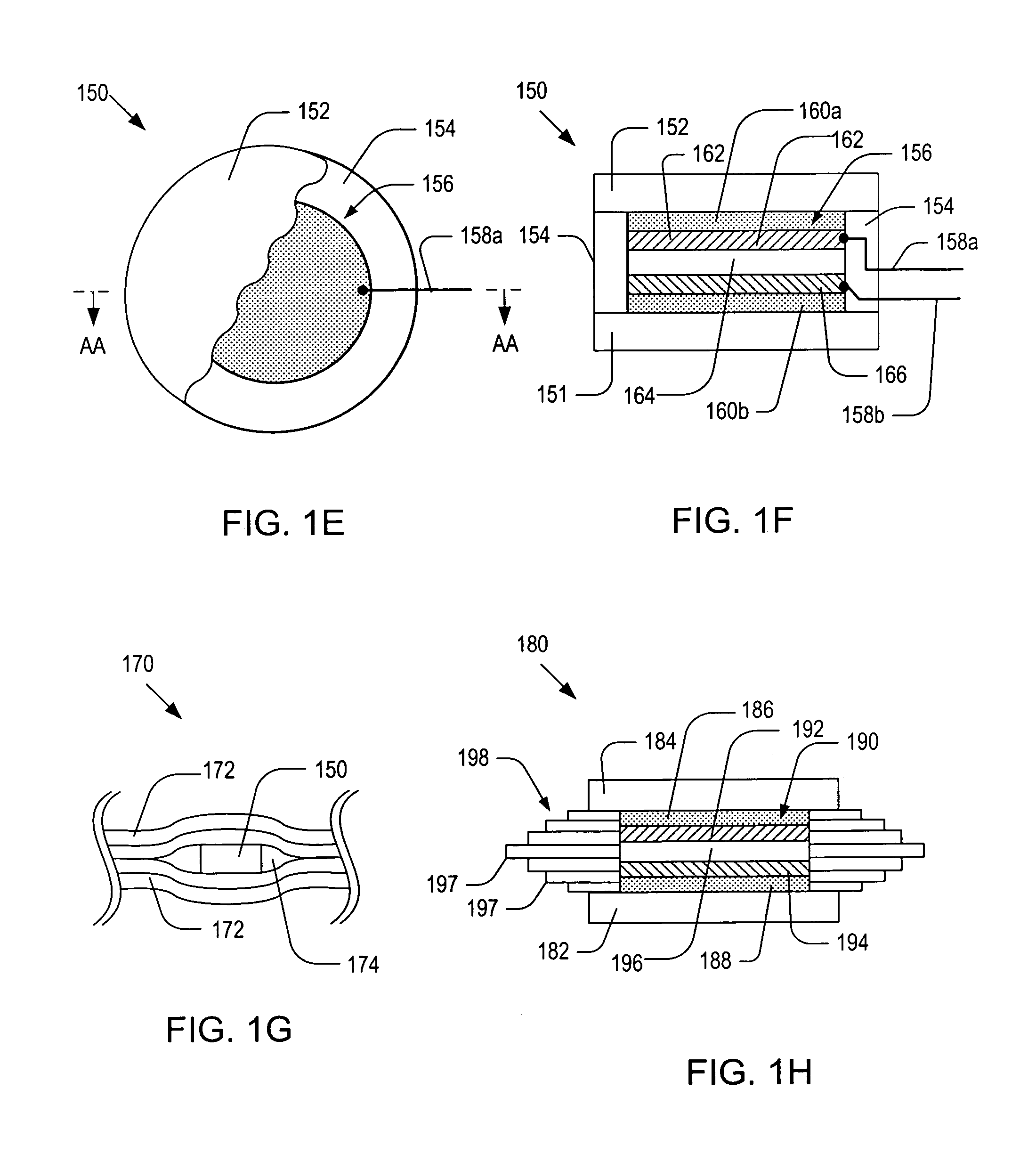
[0067]FIG. 1H is a schematic side cross-sectional view of an alternative embodiment 180 of the patch sensor 150 of FIG. 1E. As illustrated, the patch sensor 180 may include: a bottom substrate 182; a top substrate 184; a hoop layer 198; a piezoelectric device 190; top and bottom buffer layers 192 and 194; and the piezoelectric device 196. For simplicity, a pair of wires connected to the piezoelectric device 190 is not shown in FIG. 1H. The piezoelectric device 190 may include: a piezoelectric layer 196; a bottom conductive flake 194; and a top conductive flake 192. The functions and materials for the components of the patch sensor 180 may be similar to those of their counterparts of the patch sensor 150.
[0068] The hoop layer 198 may have one or more sublayers 197 of different dimensions so that the outer contour of the hoop layer 198 may match the geometry of cavity 174. By filling the cavity 174 with sublayers 197, the adhesive material may not be accumulated during the curing proc...
embodiment 318
[0080]FIG. 3C a schematic top cut-away view of the optical fiber coil 308 contained in the optical fiber patch sensor of FIG. 3A, illustrating a method for rolling the optical fiber cable 312. As shown in FIG. 3C, the outermost loop of the optical fiber coil 308 may start with one end 310a while the innermost loop may end with the other end 310b. FIG. 3D a schematic top cut-away view of an alternative embodiment 318 of the optical fiber coil 308 shown in FIG. 3C. As shown in FIG. 3D, the optical fiber cable 322 may be folded and rolled in such a manner that the outermost loops may start with both ends 320a-b. The rolled optical fiber cable 322 may be covered by a coating layer 319.
[0081] It is noted that the optical fiber coils 308 and 318 show in FIGS. 3C-D may be attached directly to a host structure and used as optical fiber coil sensors. For this reason, hereinafter, the terms “optical fiber coil” and “optical fiber coil sensor” will be used interchangeably. FIGS. 3E-F are alter...
PUM
| Property | Measurement | Unit |
|---|---|---|
| temperature | aaaaa | aaaaa |
| thickness | aaaaa | aaaaa |
| loop diameter | aaaaa | aaaaa |
Abstract
Description
Claims
Application Information
 - R&D
- Intellectual Property
- Life Sciences
- Materials
- Tech Scout
- Unparalleled Data Quality
- Higher Quality Content
- 60% Fewer Hallucinations
Browse by: Latest US Patents, China's latest patents, Technical Efficacy Thesaurus, Application Domain, Technology Topic, Popular Technical Reports.
© 2025 PatSnap. All rights reserved.Legal|Privacy policy|Modern Slavery Act Transparency Statement|Sitemap|About US| Contact US: help@patsnap.com


