Unit of the transmission of data in a serial bidirectional bus

a serial bidirectional bus and data technology, applied in digital transmission, data switching by path configuration, electrical apparatus, etc., can solve the problems of reducing the data transmission rate, erroneous data transmission needs to be expected, and the evaluation circuit required for data transmission is comparatively complex in its constructional configuration, so as to achieve high data transmission security, the effect of high data transmission ra

Active Publication Date: 2007-01-11
B&R IND AUTOMATION GMBH
View PDF18 Cites 4 Cited by
  • Summary
  • Abstract
  • Description
  • Claims
  • Application Information

AI Technical Summary

Benefits of technology

[0005] By providing the synchronization of the bus subscribers via a received data frame it is not only possible to omit control signals in contrast to the state of the art, but it is also possible in a simple way to inform the respective bus subscribers when the bidirectional bus may be used for the own data transmission. For such a data transmission, the bus subscriber at least at the bus end comprises a control stage which can be activated b the received data frame and which triggers the send device depending on the receipt of the data frame within the terms of dispatching a data frame for at least the data

Problems solved by technology

It has been noticed however that in a large number of cases, especially in the case of low signal-to-noise ratios in the signal transmission or even in the case of large distances between the bus subscribers, the evaluation circuit required for the data transmission is comparatively complex with respect to its constructional configuration.
An addition

Method used


Image

  • Unit of the transmission of data in a serial bidirectional bus
  • Unit of the transmission of data in a serial bidirectional bus
  • Unit of the transmission of data in a serial bidirectional bus

Examples


Embodiment Construction

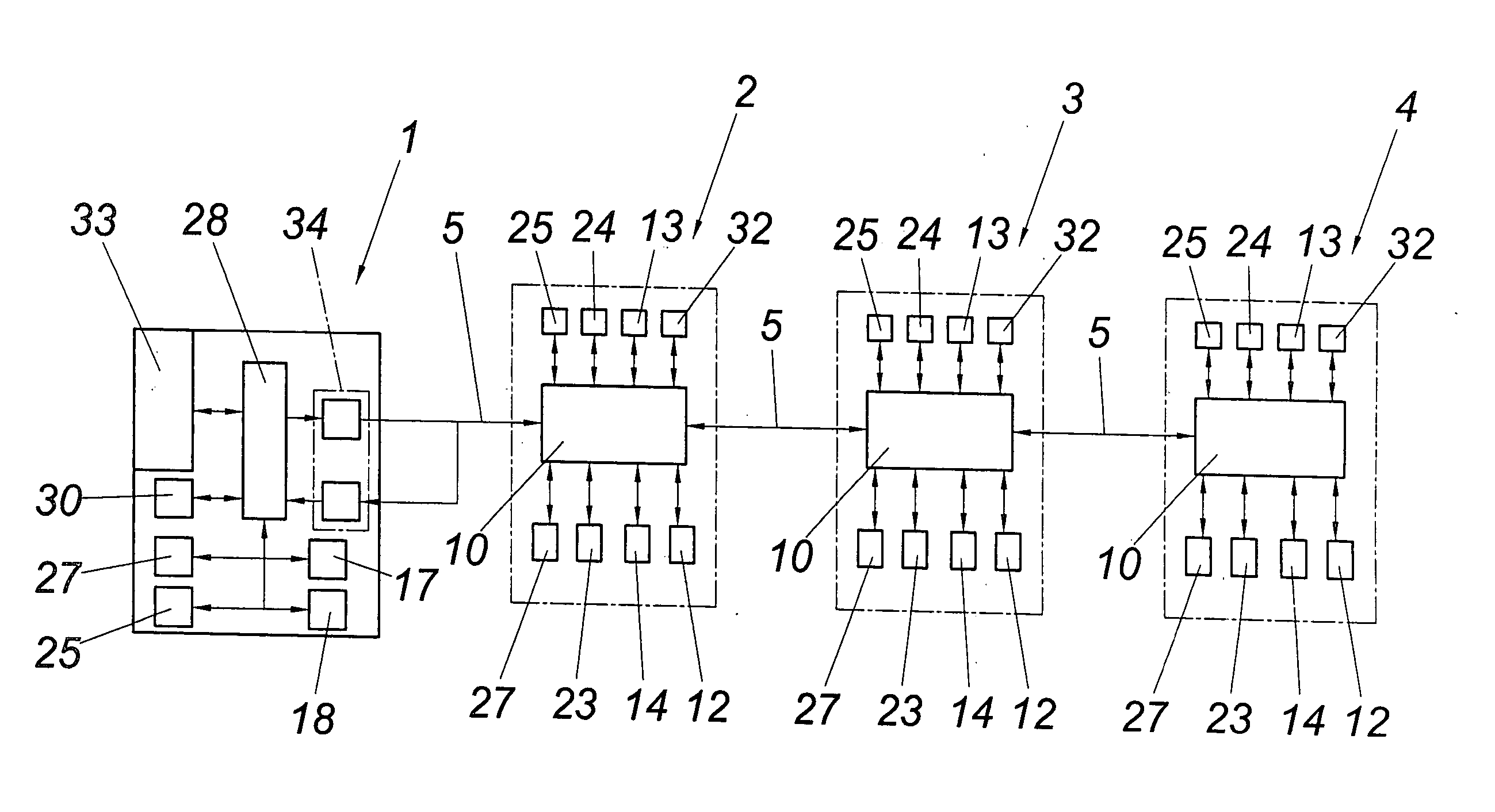
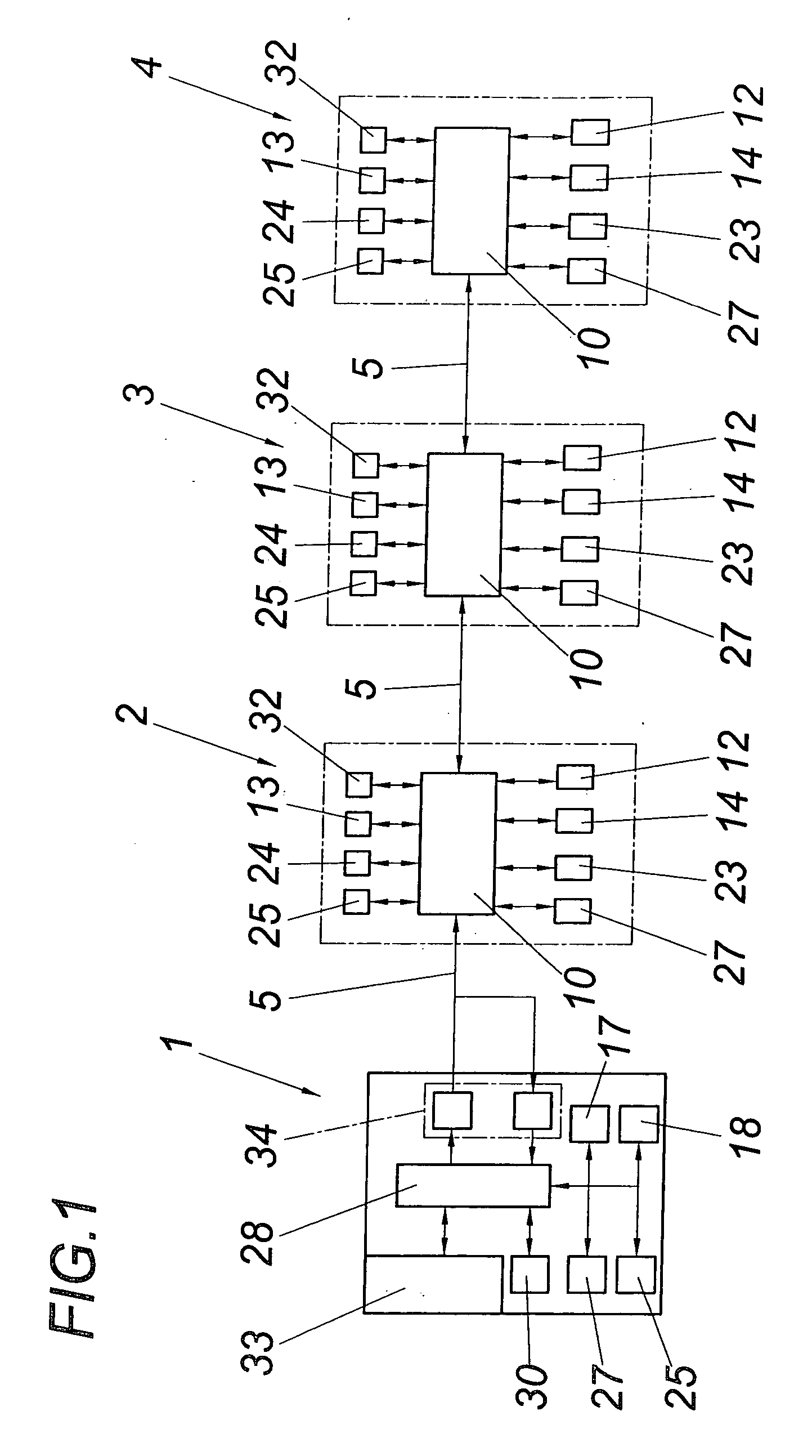
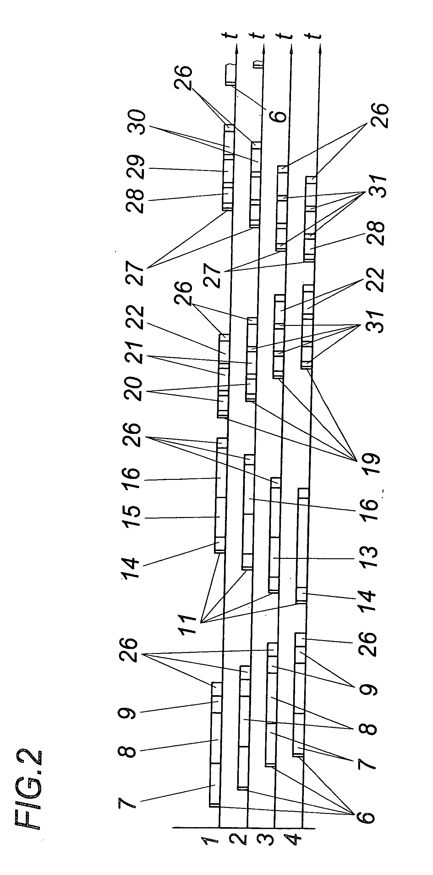
[0015] According to the illustrated embodiment, the serial bus comprises a control device 1 and three bus subscribers 2, 3 and 4 which are connected with each other via a bidirectional line 5. A send and receiving unit 34 of the control device 1 sends to the bus subscribers 2, 3 and 4 according to FIG. 2 a data frame 6 with data fields 7, 8 and 9 for the bus subscribers 2, 3 and 4. The data frame 6 is received in a time-offset manner by the bus subscribers 2, 3 and 4, wherefrom the bus subscribers 2, 3 and 4 take their respective data fields 7, 8 or 9 via en evaluation stage 10 because the bus subscribers 2, 3 and 4 know the respective position of their data fields 7, 8, 9, 14, 15 or 16 of data frame 6, 11 to be read in or out. When a data frame 6 is received by bus subscriber 4 at the end of the bidirectional serial bus opposite of the control device 1, said bus subscriber 4 sends a data frame 11 via its send device 12 in the direction of control device 1. For this purpose, the bus...


PUM


Abstract

A system is described for transmitting data in a serial bidirectional bus with a control device (1) comprising a send and receiving unit (34) for data fields (7, 8 and 9) combined into a data frame (6), and with bus subscribers (2, 3 and 4) which comprise an evaluation circuit (10) for reading in and reading out data fields (7, 8, 9, 14, 15 or 16) in data frames (6, 11), with at least the bus subscriber (4) at the bus end opposite of the control device (1) comprising a send device (12) for a data frame (11). In order to provide simple constructional conditions it is proposed that at least the bus subscriber (4) at the end of the bus comprises a control stage (13) which is activated by a received data frame (6) and triggers the send device (12) depending on the receipt of a data frame (6) within the terms of the transmission of a data frame (11) for at least the data fields (14, 15 and 16) of the bus subscribers (2, 3 and 4).

Description

FIELD OF THE INVENTION [0001] The invention relates to a system for transmitting data in a serial bidirectional bus with a control device comprising a send and receiving unit for data fields combined into a data frame, and with bus subscribers that comprise an evaluation circuit for reading in and reading out data fields in data frames, with at least the bus subscriber at the bus end opposite of the control device comprising a send device for a data frame. DESCRIPTION OF THE PRIOR ART [0002] In order to enable the synchronization of the data transmission in systems for transmitting data in a serial bidirectional bus, it is known (PCT / AT03 / 0001) to send a control signal from a control device to all bus subscribers. Following this control signal, the data transmission is commenced with a transmission to the control device, such that the bus subscriber at the bus end sends a data frame in the direction of the control device via the serial bidirectional bus. Said data frame consists at ...

Claims


Application Information

Patent Timeline
IPC IPC(8): H04L12/28H04L12/403H04L12/417
CPCH04L12/417H04L12/40032
Inventor RAINER, JOSEFBERNECKER, ERWIN
Owner B&R IND AUTOMATION GMBH
Why Eureka
Try Eureka