
Device for dispensing a controlled dose of a flowable material

a flowable material and controlled technology, applied in the direction of liquid transfer devices, instruments, volume meters, etc., can solve the problems of unnecessarily quick refilling of syringes or replacement purchases, overuse of adhesive gel-like substances, and difficulty in deciding when to stop applying adhesive gel-like substances to surfaces

Active Publication Date: 2007-01-11
SC JOHNSON & SON INC
View PDF37 Cites 93 Cited by
  • Summary
  • Abstract
  • Description
  • Claims
  • Application Information

AI Technical Summary

Benefits of technology

[0021] These and other features, aspects, and advantages of the present invention will become better understood upon consideration of the following detailed description, drawings, and appended claims.

Problems solved by technology

While these applicators do succeed in applying the adhesive gel-like substances to a surface, some users of these applicators have difficulty deciding when to stop applying the adhesive gel-like substances to a surface.
This leads to overuse of the adhesive gel-like substance and an unnecessarily quick need for refill of the syringe or replacement purchase in the case of a disposable device.
Another problem is that some users do not apply enough of the substance which minimizes efficacy of substance.

Method used


Image

  • Device for dispensing a controlled dose of a flowable material
  • Device for dispensing a controlled dose of a flowable material
  • Device for dispensing a controlled dose of a flowable material

Examples


second embodiment

[0069] Turning now to FIGS. 15 to 20f, there is shown a dispensing device 110 according to the invention. The device 110 can apply controlled unitized doses of a flowable adhesive material to a surface. In one example use, the device 110 may be used for applying controlled doses of a cleaning, disinfecting and / or fragrancing flowable adhesive gel 114 to the surface of a toilet, urinal, bathtub, shower or the like. One example gel is described in U.S. Pat. No. 6,667,286. The device 110 includes a tubular body 120 that contains the flowable material 114 and a plunger 160 that pushes the flowable material from the tubular body 120 onto the surface. A cap 135 covers the tubular body opening during storage. Typically, all of the components of the device 110 are constructed from a polymeric material such as translucent or opaque polyethylene or polypropylene. A piston 150 is positioned for sealing sliding movement within the cavity 124 of the body 120. The piston 150 has an outwardly exte...

third embodiment

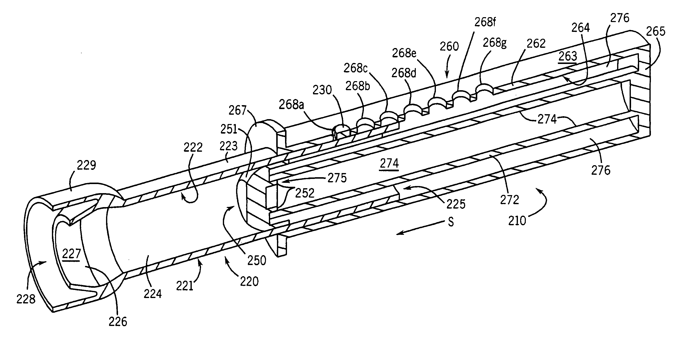
[0079] Turning now to FIGS. 21 and 22, there is shown a dispensing device 210 according to the invention. The device 210 can apply controlled unitized doses of a flowable adhesive material to a surface. In one example use, the device 210 may be used for applying controlled doses of a cleaning, disinfecting and / or fragrancing flowable adhesive gel 214 to the surface of a toilet, urinal, bathtub, shower or the like. One example gel is described in U.S. Pat. No. 6,667,286. The device 210 includes a tubular body 220 that contains the flowable material 214 and a plunger 260 that pushes the flowable material from the tubular body 220 onto the surface. A cap similar to caps 54 and 135 described above may cover the tubular body opening during storage. Typically, all of the components of the device 210 are constructed from a polymeric material such as translucent or opaque polyethylene or polypropylene. A piston head 250 is positioned for sealing sliding movement within the cavity 224 of the...


PUM


Abstract

A device for applying controlled unitized doses of a flowable material to a surface is disclosed. The device includes a tubular body and a plunger. The body has a wall defining a cavity, and the body has a first open end and an opposite second end having a dispensing orifice. A flowable material is contained in the cavity of the body. The plunger has an outer sleeve dimensioned for surrounding at least a section the body and an inner pushing structure dimensioned for axial movement in the cavity of the body. The device has means for indexed positioning of the second end of the body and an inner end of the inner pushing structure of the plunger relative to each other to provide controlled unitized doses of the flowable material to a surface when the plunger is moved toward the body by a user's hand.

Description

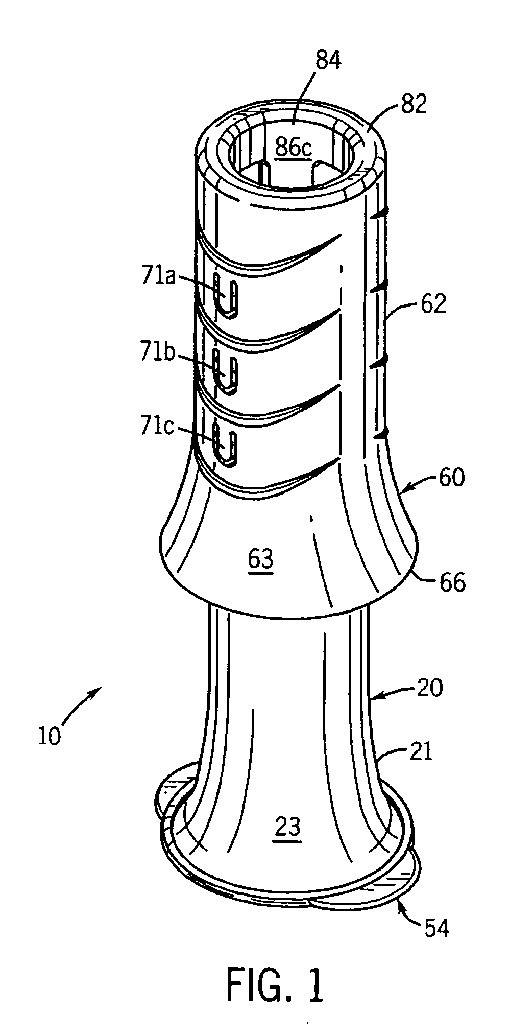
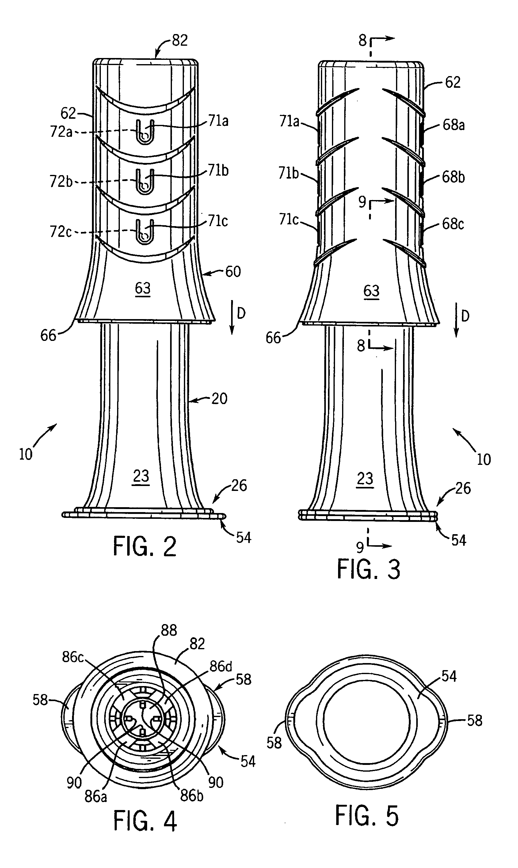
CROSS-REFERENCES TO RELATED APPLICATIONS [0001] Not Applicable. STATEMENT REGARDING FEDERALLY SPONSORED RESEARCH [0002] Not Applicable. BACKGROUND OF THE INVENTION [0003] 1. Field of the Invention [0004] This invention relates to a device for dispensing controlled doses of a flowable material, and more particularly to a device for applying controlled doses of a flowable adhesive material to a surface. [0005] 2. Description of the Related Art [0006] U.S. Pat. No. 6,667,286 describes a viscous gel-like substance that may be applied directly to the inner surface of a toilet bowl for cleaning and / or disinfecting and / or fragrancing the toilet bowl. The substance can be applied from a suitable applicator directly onto the inner surface of the toilet bowl, to which the substance adheres. The substance remains on the inner surface of the toilet bowl even after being contacted with flush water, and typically the substance is only flushed away completely after a large number of flushes. The s...

Claims


Application Information

Patent Timeline
IPC IPC(8): B67D5/22G01F11/00B67D7/22
CPCB65D83/0005C11D17/046E03D9/02E03D2009/026
Inventor JAICHANDRA, DORAISWAMIO'BRIEN, GERARD MICHAELREEVES, GEORGEKLINKHAMMER, MICHAEL E.ZACH, STEVEN A.KUBICEK, CHRIS A.WESTPHAL, NATHAN R.
Owner SC JOHNSON & SON INC
Learn More