
Automated manufacturing device and method for biomaterial fusion

Inactive Publication Date: 2007-01-04
PROVIDENCE HEALTH SYST OREGON +1
View PDF22 Cites 5 Cited by
  • Summary
  • Abstract
  • Description
  • Claims
  • Application Information

AI Technical Summary

Problems solved by technology

Unfortunately, sutures cause additional tissue damage during their placement and tying.
Sutures also result in the introduction of a foreign material into the body, increasing the risk for further damage or rejection.
Moreover, sutures do not necessarily result in a water tight seal and may require a long healing time.
The placement of sutures involves a complicated set of movements that may be difficult of impossible in microsurgical or minimally invasive applications.
The absorbed energy results in a molecular alteration of the affected biomaterial and causes bonds to form between neighboring biomaterials.
Accurate determination of optimal laser parameters is difficult in this model.
Furthermore, manual control of laser positioning and movement can, and often does, lead to under or overexposure of tissues / biomaterials to laser energy which can cause failed welds.
The variation in technique among operators makes accurate research difficult, if not impossible, and the lack of standardized irradiation patterns and dosages only adds to the inconsistency of welding procedural success.
However, the use of such devices is often associated with thrombosis and other complications.
Suturing is a poor technique for joining multiple layers of biomaterial.
While suturing is adequate to join the biomaterial sheets to the metallic frame, the frame-sutured multiple sheets are not joined on their major surfaces and are therefore subject to leakage between the layers.
Suturing of the major surfaces of the biomaterial layers also introduces holes into the major surfaces, increasing the risk of conduit fluid leaking through or a tear forming in one of the surfaces.
However, this approach is disadvantageous from manufacturing and implantation perspectives.
Suturing is time-consuming and labor-intensive.
It is also an operator dependent process that can lead to issues with product uniformity and reliability.
As well, suturing entails repeatedly piercing the biomaterial, creating numerous tiny punctures that can weaken the biomaterial and potentially lead to leakage and infection after the graft device has been installed.
Moreover, the presence of suture material can enhance the foreign body response and lead to tubular vessel narrowing at the implantation site.
However, the references fail to teach crosslinking of collagen fibrils between two individual collageneous materials, as well as fusion of those separate materials using photo-oxidization techniques.

Method used


Image

  • Automated manufacturing device and method for biomaterial fusion
  • Automated manufacturing device and method for biomaterial fusion
  • Automated manufacturing device and method for biomaterial fusion

Examples


Embodiment Construction

)

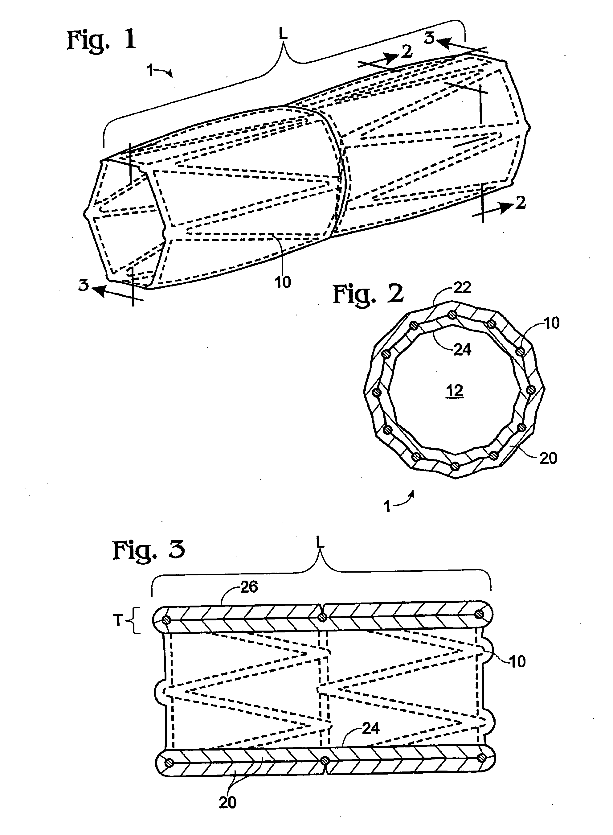
[0024] Implantable stents and grafts are disclosed in Applicant's U.S. Ser. No. 10 / 104,391. The stent graft 1 therein comprises a typically cylindrical stent frame 10 having a length L and defining a lumen 12. The stent graft further has a sheath of biomaterial 20 suturelessly attached to and substantially covering the stent frame.

[0025] The stent frame 10 preferably is constructed of a fine-gauge metal (e.g., 0.014 inch diameter) of a flexible character. Such frame enables the stent graft to be expanded or compressed in diameter or length.

[0026] The stent frame is covered with a biomaterial sheath 20 having a selected thickness T. The biomaterial sheath can comprise a single layer, a single layer with a partial overlap, or a plurality of layers (single or multiple sheets) coupled to the supporting stent frame. The sheath of biomaterial preferably comprises both the inner stent graft surface 24 and the outer stent graft surface 26.

[0027] If the biomaterial sheath is constructed ...


PUM

PropertyMeasurementUnit
Wavelengthaaaaaaaaaa
Lengthaaaaaaaaaa
Lengthaaaaaaaaaa

Abstract

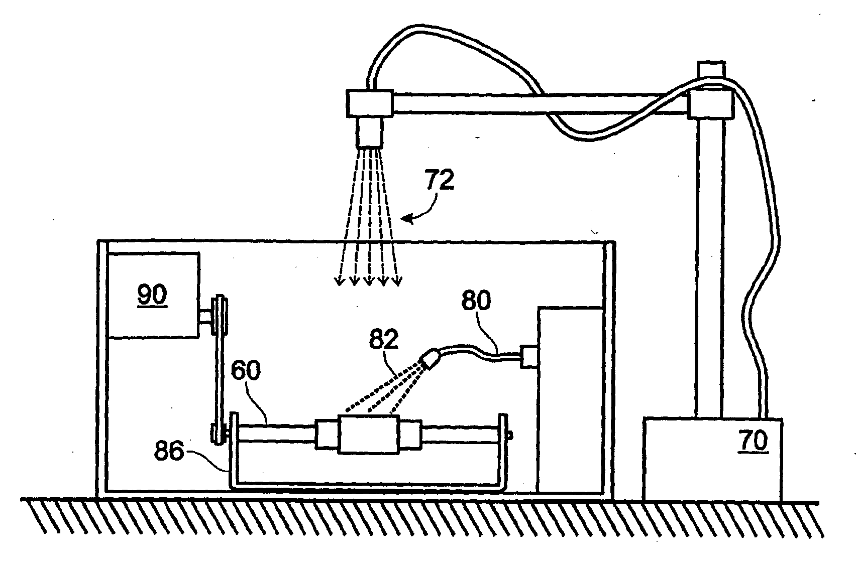
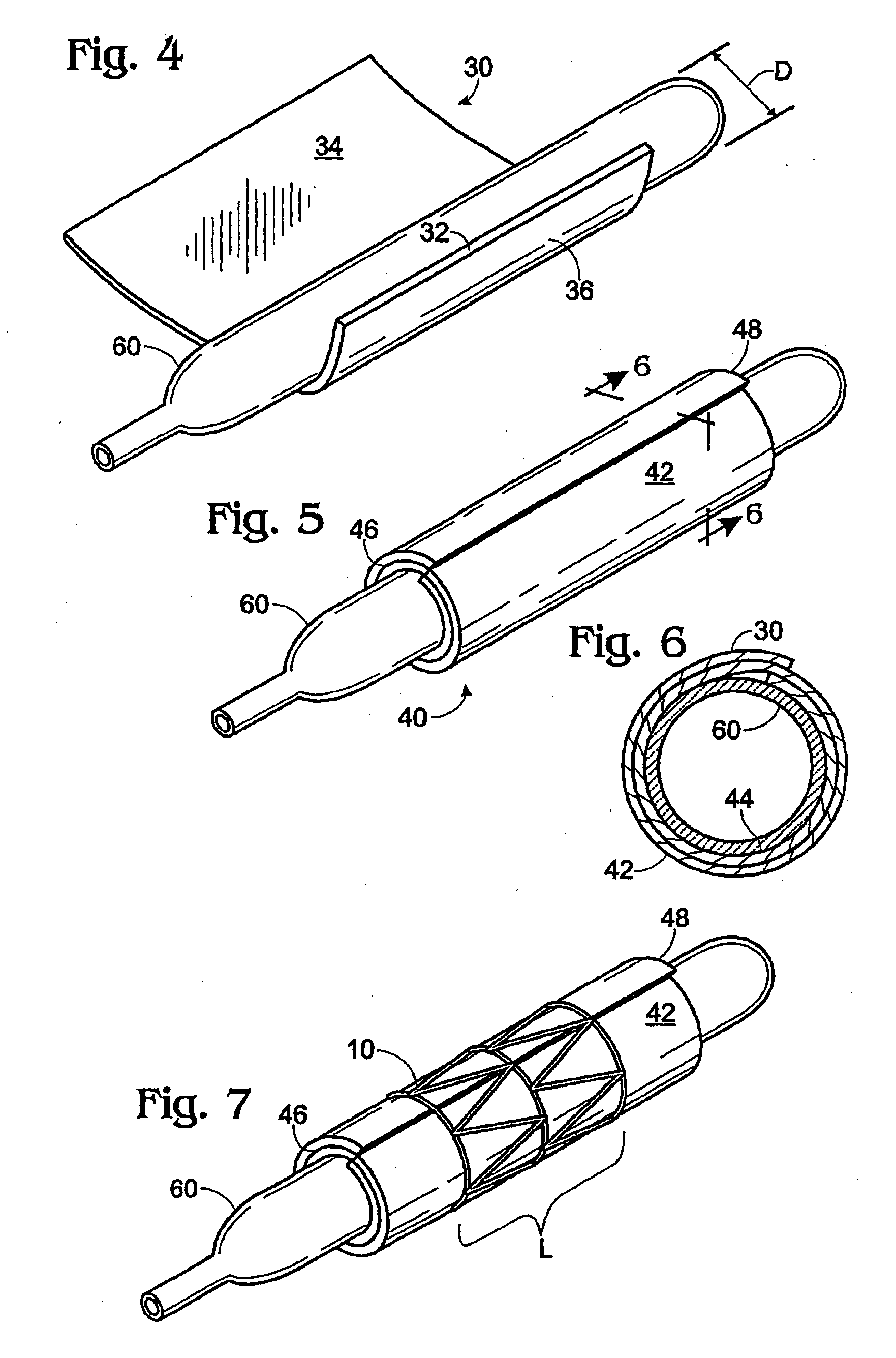
An apparatus for making a bioprosthetic stent graft is disclosed, the stent having a stent frame and a biomaterial sheath suturelessly bonded to the stent frame. An automated energy irradiator guidance system is disclosed which reduces the potential for human error and improves the consistency and repeatability of tissue welding techniques. The system includes a mapper, a patternizer, an energy director and can additionally include an energy regulator. An interface is included, allowing pattern creation, selection and editing by a user. The system further provides control of energy irradiator parameters for use in tissue welding.

Description

CROSS REFERENCE TO RELATED APPLICATIONS [0001] This application is a continuation-in-part of and claims priority from each of U.S. Ser. No. 10 / 132,079, filed on Apr. 24, 2002, and U.S. Ser. No. 10 / 104,391, filed on Mar. 21, 2002, the subject matter of which are incorporated by reference for all purposes.[0002] This invention was made with U.S. Government support under Grant Number DAMD17-96-6006, awarded by the Army Medical Research and Materiel Command. The U.S. Government may have certain rights in the invention.BACKGROUND OF THE INVENTION [0003] The present invention is related to the field of stents, and more specifically to a stent device and method for automated sutureless biomaterial bonding in the manufacture of such stents. [0004] Tissue closure is most commonly performed using sutures, which are inexpensive, reliable, and readily available. Unfortunately, sutures cause additional tissue damage during their placement and tying. Sutures also result in the introduction of a f...

Claims


Application Information

Patent Timeline
IPC IPC(8): B29C35/08
CPCA61F2/07B29C66/494A61F2002/828B29C53/562B29C65/1616B29C66/1142B29C66/90B29C67/0018B29L2031/7534B29C65/1677A61F2/89A61F2002/075B29C65/1454B29C65/1654B29C66/1222B29C66/1224B29C66/4322B29C66/49A61F2002/072
Inventor AHLE, KAREN MARIEBASINGER, BROOKE C.SWEET, CYNDIA A.MARTIN, BENJAMIN CHARLESJOHANSEN, ELIZABETH WHITNEYCAMP, JASON DEGREGORY, KENTON W.
Owner PROVIDENCE HEALTH SYST OREGON
Learn More