
Object proximity warning system

a proximity warning and object technology, applied in the field of objects proximity warning systems, can solve the problems of difficult maneuverability of vehicles in crowded locations, difficulty in maintaining constant surveillance of all such exposed parts at the same time, and frequent damage to vehicles that are stationary or parked

Inactive Publication Date: 2006-12-21
PASHKO PASCHENKO DIMITRI
View PDF24 Cites 61 Cited by
  • Summary
  • Abstract
  • Description
  • Claims
  • Application Information

AI Technical Summary

Benefits of technology

"The Object Proximity Warning System is a system that can detect objects or obstacles that may collide with a vehicle and alert the operator of the vehicle to the threat. The system uses sensors to determine the distance between the vehicle and the object, and display and alerting means to inform the operator of the vehicle of the proximity of the object. This system can be used in both active and passive warning systems. Additionally, the system can also provide information to the operator of a load-handling vehicle with respect to the closeness of approach of the load-engaging means to the load. The technical effects of this system include improving safety and preventing collisions."

Problems solved by technology

Other vehicles have multiple parts which can potentially impact objects in the vehicle's surroundings, so that it is difficult for the operator to maintain constant surveillance of all such exposed parts simultaneously.
Such vehicles are difficult to maneuver in crowded locations such as may be encountered in parking or storing the vehicle, or to approach a loading dock, dock or similar structure.
Furthermore, vehicles that are stationary or parked are frequently at risk from damaging contact from another vehicle moving in the vicinity of the stationary vehicle.
In addition to the obstacle-avoidance applications outlined above, there are situations where the normal operation of a vehicle may involve picking up a load or object and where the region of contact between vehicle and load or object cannot be seen by the operator.
Lumber-handlers (vehicles with high clearance which straddle a stack of lumber and lift it for transport to another site) and some fork lifts, particularly high-lift fork lifts, suffer from this problem.
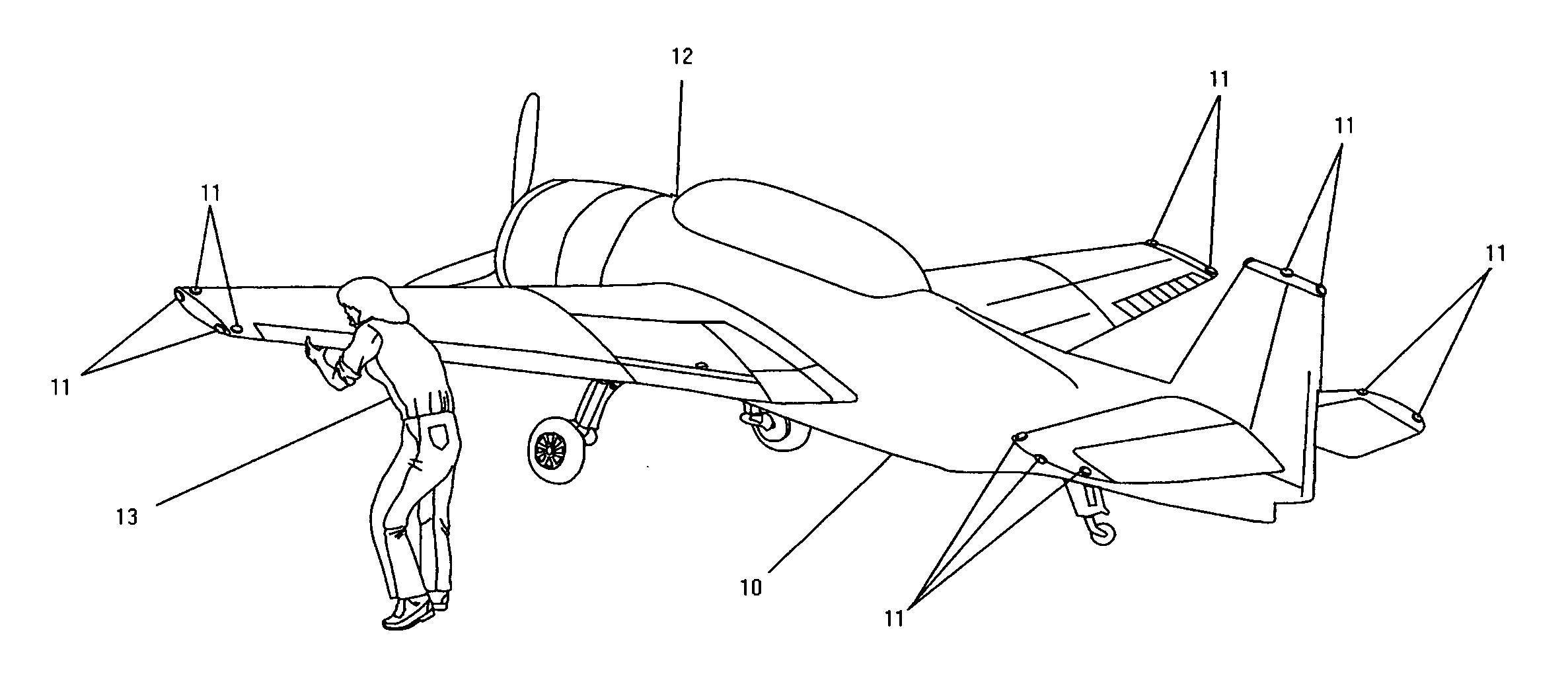
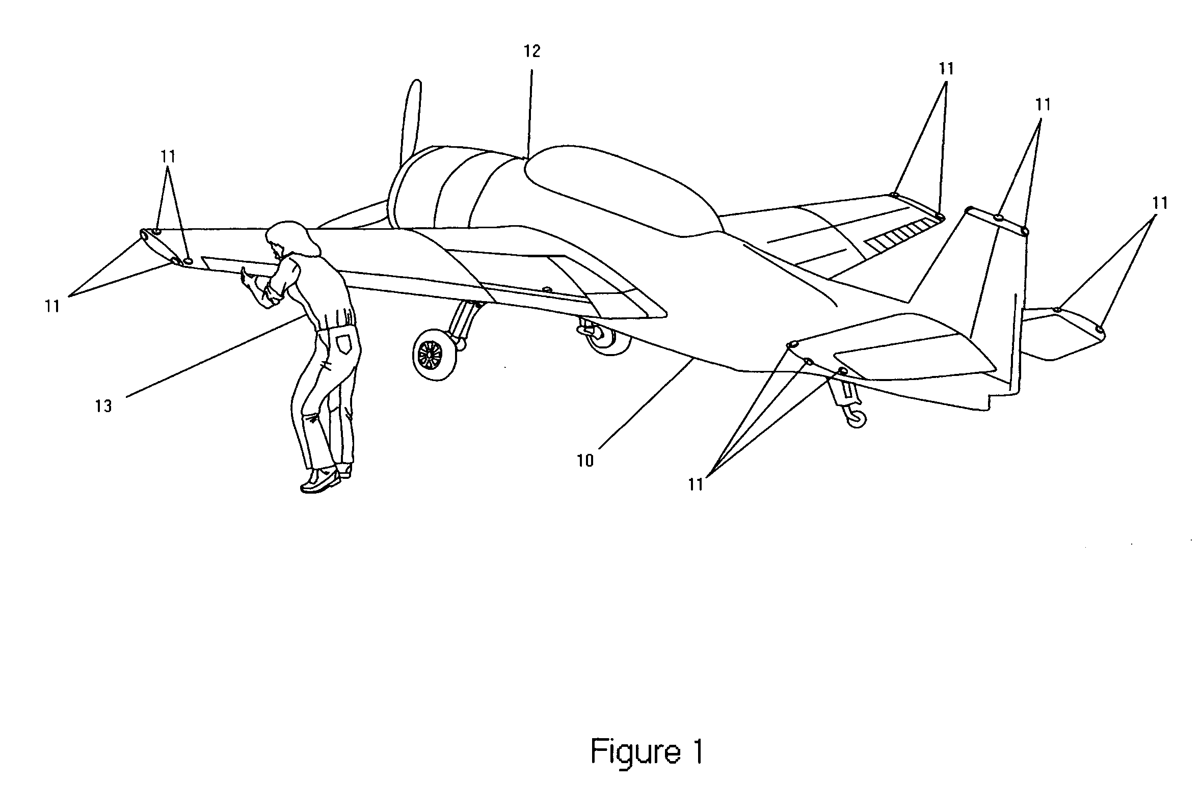
A particularly serious problem is encountered in operation of aircraft on the ground during such operations as taxiing, parking, docking, hangaring, and other operations requiring the positioning of an aircraft on the ground in congested areas.
And since even a minor collision can do extensive damage which is very expensive to repair, the importance of avoiding collision is very high.
There is also the additional hazard to aircraft in the use of service vehicles, such as baggage loaders, catering vehicles, sanitary service vehicles, fueling vehicles, etc., which must approach close to a parked aircraft, and which are often of such construction that visibility of the area between vehicle and aircraft is limited or non-existent.
Several instances of collisions between baggage loading vehicles and commercial aircraft have recently occurred, resulting in damage to the aircraft which did not become apparent until the aircraft was airborne, and requiring emergency landings.
A similar problem exists for many ships and boats, where close approach to such objects as docks and lock walls may be necessary, and where surveillance of blind spots which might impact such objects with damaging force is needed.
Such systems are typically designed to provide warnings of objects one or more car lengths distant, and lack the spatial resolution and distance-of-approach resolution to permit maneuvering in crowded environments, parking, garaging / hangaring, etc.
Such systems would not be applicable to maneuvering aircraft on the ground in crowded airports in such a way as to avoid collisions.

Method used


Image

  • Object proximity warning system
  • Object proximity warning system

Examples


Embodiment Construction

[0027] The Object Proximity Warning System of the present invention comprises one or more distance-determining sensors together with display and alerting means responsive to said sensors to provide information to the operator of a subject vehicle with respect to the closeness of approach of the subject vehicle to an object, or the closeness of approach of another vehicle to the subject vehicle. In active embodiments of the present invention, said sensors will be comprised in a subject vehicle, and will provide information to the operator of the vehicle, or to the operators of other vehicles moving in the vicinity of the subject vehicle, with respect to the closeness of approach of the vehicle to virtually any object. In passive embodiments, said sensor or sensors will be comprised in objects with which a vehicle might collide, and will provide information to vehicle operators with respect to closeness of approach to virtually any vehicle.

[0028] In other embodiments, the Object Prox...


PUM


Abstract

A system and method are provided to detect an impending contact or collision between a subject vehicle, which may be an aircraft, a watercraft or a load-handling vehicle, and stationary objects or other vehicles in the vicinity of the subject vehicle, comprising distance or motion-detecting sensors mounted at positions on the subject vehicle at risk of such collision or contact, and alerting means, responsive to said sensors, to notify the operator of the subject vehicle and / or the operators of such other vehicles in the vicinity of the subject vehicle of the risk of a collision. Preferred embodiments comprise alerting means which indicate to the operator of the subject vehicle which, if any, sensors detect an object closer too the subject vehicle than a predetermined distance of safe approach.

Description

TECHNICAL FIELD OF THE INVENTION [0001] This invention relates to the systems for detecting an impending collision between a vehicle and an object in the vehicle's surroundings and alerting the operator to take action to avoid the collision. BACKGROUND [0002] Many vehicles have “blind spot”-parts of the vehicle that are not readily visualized by the operator. Other vehicles have multiple parts which can potentially impact objects in the vehicle's surroundings, so that it is difficult for the operator to maintain constant surveillance of all such exposed parts simultaneously. Such vehicles are difficult to maneuver in crowded locations such as may be encountered in parking or storing the vehicle, or to approach a loading dock, dock or similar structure. Vehicles with such blind spots include aircraft being maneuvered on the ground, many types of trucks; agricultural equipment such as combines, hay-balers and tractor-drawn plows, harrows, cultivators, etc; industrial specialty vehicle...

Claims


Application Information

Patent Timeline
Patent Type & Authority Applications(United States)
IPC IPC(8): G08G1/16
CPCB60Q5/006B60Q9/005G08G5/0078B60Q9/008G08G5/0021B60Q9/007
Inventor PASHKO-PASCHENKO, DIMITRI
Owner PASHKO PASCHENKO DIMITRI
Learn More