Spherical surface push-in sealing method and a sealing valve utilizing the method

a push-in sealing and sealing method technology, which is applied in the direction of valve details, valve arrangement, valve operating means/release devices, etc., can solve the problems of reducing the pretightening force of the seal surface, reducing the sealing effect, and only having a sealing function, so as to achieve reliable and constant sealing properties, simple structure, and simple structure

Inactive Publication Date: 2006-12-21
DONG YONGBIN
View PDF8 Cites 3 Cited by
  • Summary
  • Abstract
  • Description
  • Claims
  • Application Information

AI Technical Summary

Benefits of technology

[0005] The present invention provides a spherical surface push-in sealing method. According to the method, it is possible to close and open the spherical seal, and simultaneously retain appropriate pretightening force of the seal surface. To achieve this goal, a valve core is provided with a spherical surface to engage a seal base, wherein an initial position is arranged for the valve core so that the valve core is retained in the initial position before use. While in use, the valve core is pushed out of the initial position by a forward axial force. The valve core moves axially in the valve chamber under the action of the axial forces to close and open the seal. By adopting this method, the pretightening force of the seal surface can be regulated according to different needs, thus, the seal is reliable. In addition, there is no friction between the seal surfaces and the seal surface is not subject to wearing, so the sealing effect is constant. Furthermore, compared with the conventional seal methods, the sealing method provided by the present invention can be used more broadly. It can be used not only for a non-refillable sealing valve but also for a refillable sealing valve.
[0008] The present invention is also aimed to provide a sealing valve using the aforementioned sealing method. To achieve this purpose, the sealing valve is provided with a valve body, a valve core, a seal base, wherein the commensurate fitting surfaces of the valve core and the seal base are spherical surfaces, an elastic stand for the valve core is arranged in the valve body and corresponding to an initial position for the valve core, a rod is arranged behind the valve core, and an opening is arranged on the valve chamber to communicate with outside. By adopting this structure, the sealing valve provided by the present invention has a simple structure, and the spherical seal can be closed and opened. Furthermore, the pretightening force of the seal surface can be regulated according to different needs, and the sealing property is reliable and constant. The sealing valve provided by the present invention can be used not only as a non-refillable sealing valve, but also as a refillable sealing valve after arranging a spring between the valve core and the seal base.

Problems solved by technology

Therefore, the fastening sealing method only has a sealing function.
However, the pretightening force of the seal surface will decrease with the increase of the opening and closing times. Thus, the sealing effect will decline and leakage may finally occur.

Method used


Image

  • Spherical surface push-in sealing method and a sealing valve utilizing the method
  • Spherical surface push-in sealing method and a sealing valve utilizing the method
  • Spherical surface push-in sealing method and a sealing valve utilizing the method

Examples


first embodiment

The First Embodiment

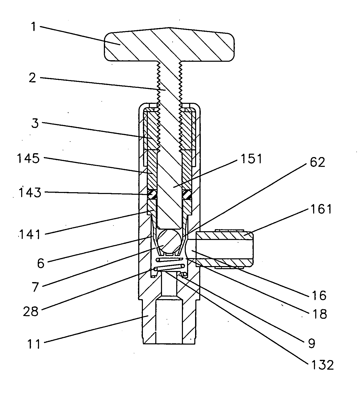
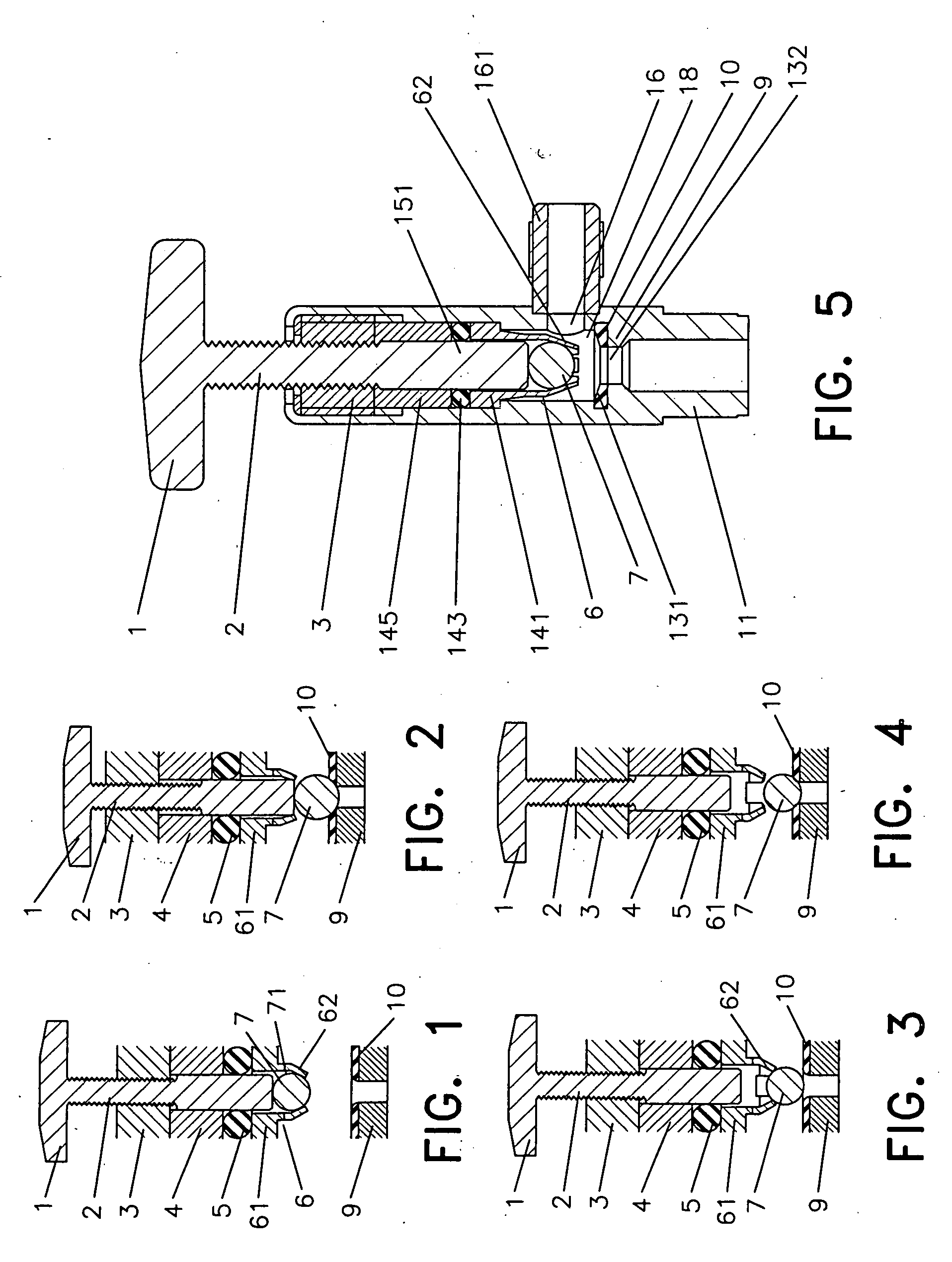
[0021] Referring to FIG. 1, the valve core 7 of the present invention is provided with a spherical surface to fit the seal base 9, wherein an initial position 71 for the valve core 7 is located, so that the valve core 7 is retained in the initial position71 before use. While in use, the valve core 7 is pushed out of the initial position 71 by a forward axial force, so that the valve core moves axially in a valve chamber under the action of the axial forces to close and open the seal opening.

[0022] In this embodiment, the direction from the valve core 7 to the seal base 9 is defined as the forward direction, and the opposite direction is defined as the backward direction. Accordingly, the front end and the rear end of the valve core 7 can be distinguished. In addition, the forward movement and backward movement of the valve core 7 are the axial movements of the valve, and the forces acting on the valve core 7 in this direction are the axial forces acting on the v...

second embodiment

The Second Embodiment

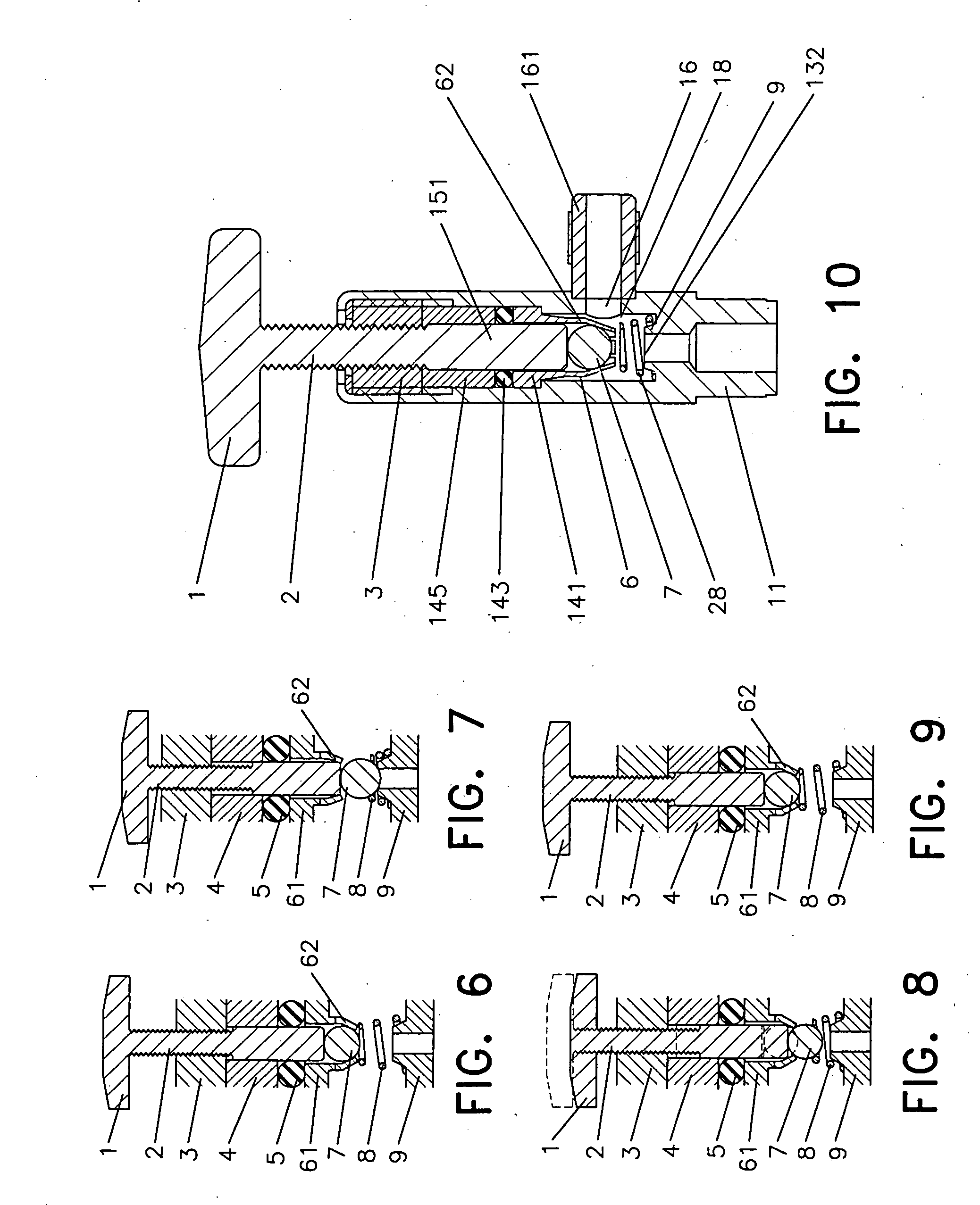
[0033] In this embodiment, a spring is added between the valve core and the seal base on the basis of the method provided by the first embodiment. In FIG. 6 to FIG. 9, the reference numerals are the same as those of FIG. 1 to FIG. 4 to represent the same parts.

[0034] This embodiment demonstrates the sealing method provided by the present invention when used for re-filling situations. FIG. 6 is a schematic drawing of this embodiment when the valve core is in the initial position. In FIG. 7, the rod moves forward and pushes the valve core onto the seal base to place the valve in the sealing state. In FIG. 8, the rod moves backward, and the forward push force on the valve core exerted by the rod is removed, the valve core is gradually pushed up by a spring 8. If the medium pressure difference between the front end and the rear end of the valve core still exists, a push force acting on the valve core in the same direction as the spring 8 will be generated.

[0035]FI...


PUM


Abstract

The invention provides a spherical surface push-in sealing method using a valve core with a spherical surface to engage a seal base, wherein an initial position is arranged for the valve core, so that the valve core is retained in the initial position before use. When in use, the valve core is pushed out of the initial position by a forward axial force. The valve core moves axially in the valve chamber under the action of the axial forces to close and open the seal. The invention also provides a sealing valve using the sealing method comprising a valve body, a valve core, a seal base. The engaging surface of the valve core and the seal base being a spherical surface, wherein an elastic stand for the valve core is arranged in the valve body and opposite to the initial position for the valve core, a rod is arranged behind the valve core, and an opening is arranged on the valve chamber to communicate with the outside. The pre-tightening force of the seal surface of the invention can be regulated according to different needs. The seal is reliable and constant, and can be used for both the non-refillable sealing valve and the refillable sealing valve.

Description

BACKGROUND OF THE INVENTION [0001] 1. Field of the Invention [0002] The invention relates to a method for sealing pressure containers and the technology of sealing valves, particularly the fastening seals, pressure container seals and valve seals. [0003] 2. Description of the Related Art [0004] Presently, most of the known spherical sealing methods utilize either fastening or rotating elements. The fastening sealing method employs a fastening member to press a spherical object with a seal base. The spherical object and the seal base cannot move relative to each other during use. Therefore, the fastening sealing method only has a sealing function. On the other hand, in the rotating sealing method, the spherical object can be moved during use, and the functions of closing and opening the seal surface can be achieved by using channels or spherical surfaces on the spherical object. However, the pretightening force of the seal surface will decrease with the increase of the opening and cl...

Claims


Application Information

Patent Timeline
IPC IPC(8): F16K31/44
CPCF16K1/302F16K1/14
Inventor DONG, YONGBIN
Owner DONG YONGBIN
Why Eureka
Try Eureka