
Rearview mirror with non-parallel viewing areas

a rearview mirror and viewing area technology, applied in mirrors, instruments, vehicle components, etc., can solve the problems of affecting the viewing area, causing significant distortion of the viewing area, and unable to detect objects in the conventional rearview mirror system, so as to increase the driver's ability to view

Inactive Publication Date: 2006-12-14
STARBUCK GARY T
View PDF9 Cites 34 Cited by
  • Summary
  • Abstract
  • Description
  • Claims
  • Application Information

AI Technical Summary

Benefits of technology

[0008] It is the object of the present invention to provide a side rearview mirror that is mounted to the exterior of a vehicle that substantially increases the driver's ability to view objects in the driver's blind spot.
[0009] It is a further object of the present invention to provide a rearview mirror that is mounted to the exterior of a vehicle that utilizes an angular portion to provide substantial viewing of objects in the driver's blind spot.
[0011] A further object of the present invention is to provide a rearview mirror that is mounted to the exterior of a vehicle that substantially increases the vision objects in the driver's blind spot that inhibits distortion of the image of these objects.

Problems solved by technology

Conventional rearview mirror systems are unable to detect objects that are located in the blind spot that is adjacently rearward of each side of the vehicle.
Improper vision of this area leads to thousands of vehicle accidents each year.
Current devices utilized to enhance a driver's vision of their blind spot create significant distortion of the viewing area.
This can create a potential safety hazard as the driver temporarily is not focused on the environment immediately in front of the vehicle.
Additionally, many drivers with neck or back disabilities cannot successfully maneuver in order to perform an appropriate check for any objects in their blind spot.

Method used


Image

  • Rearview mirror with non-parallel viewing areas
  • Rearview mirror with non-parallel viewing areas
  • Rearview mirror with non-parallel viewing areas

Examples


Embodiment Construction

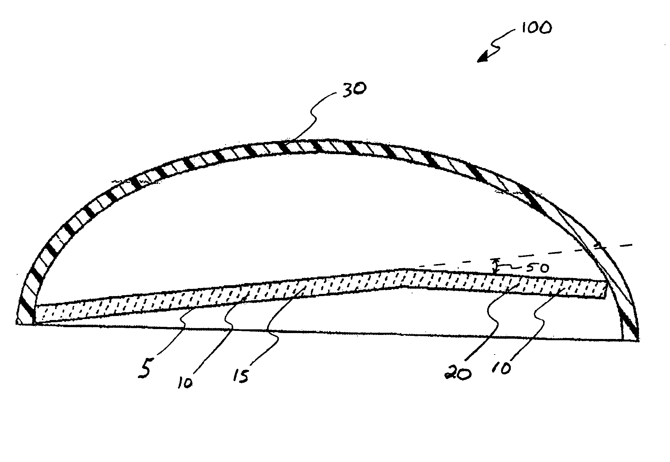
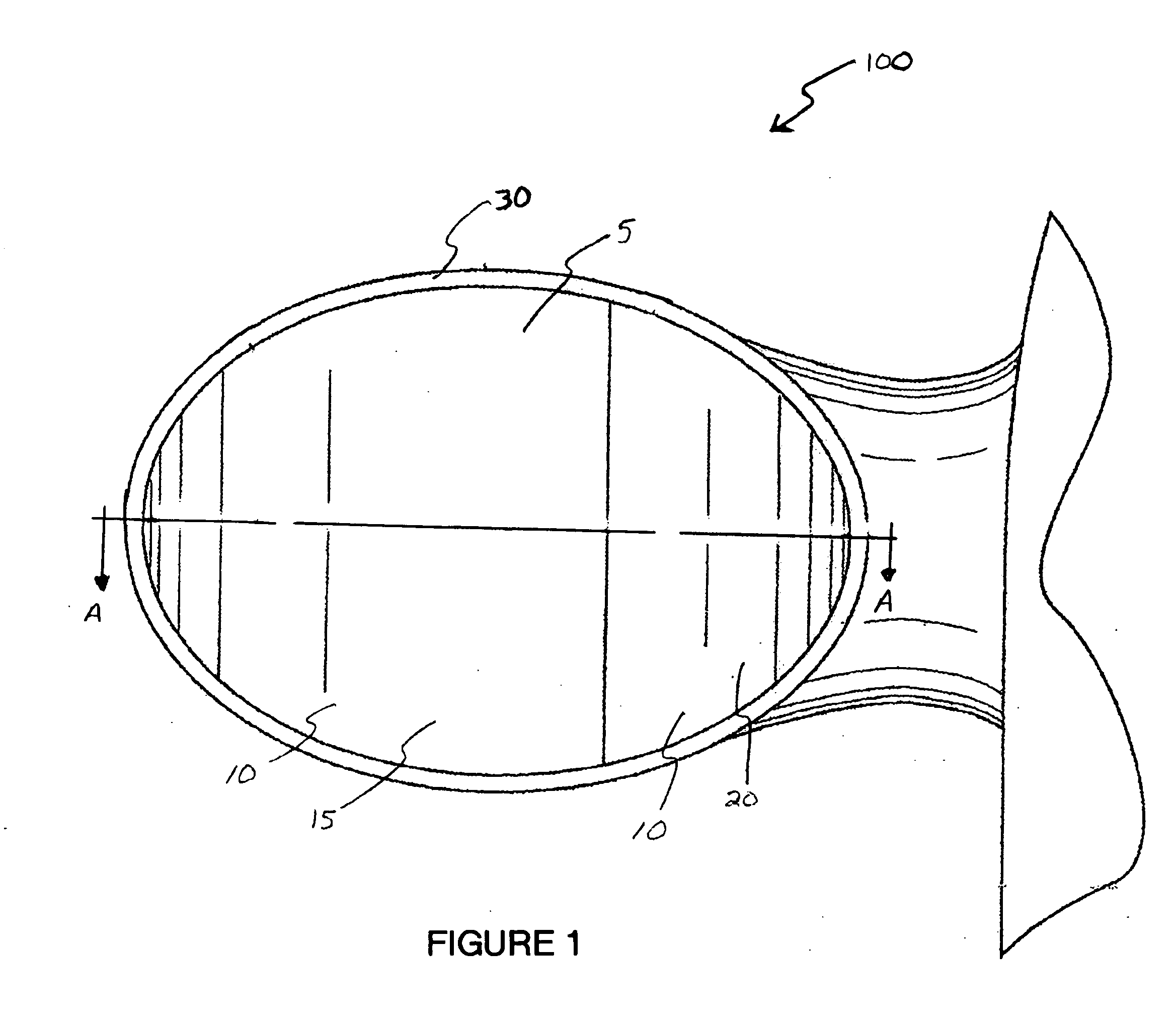
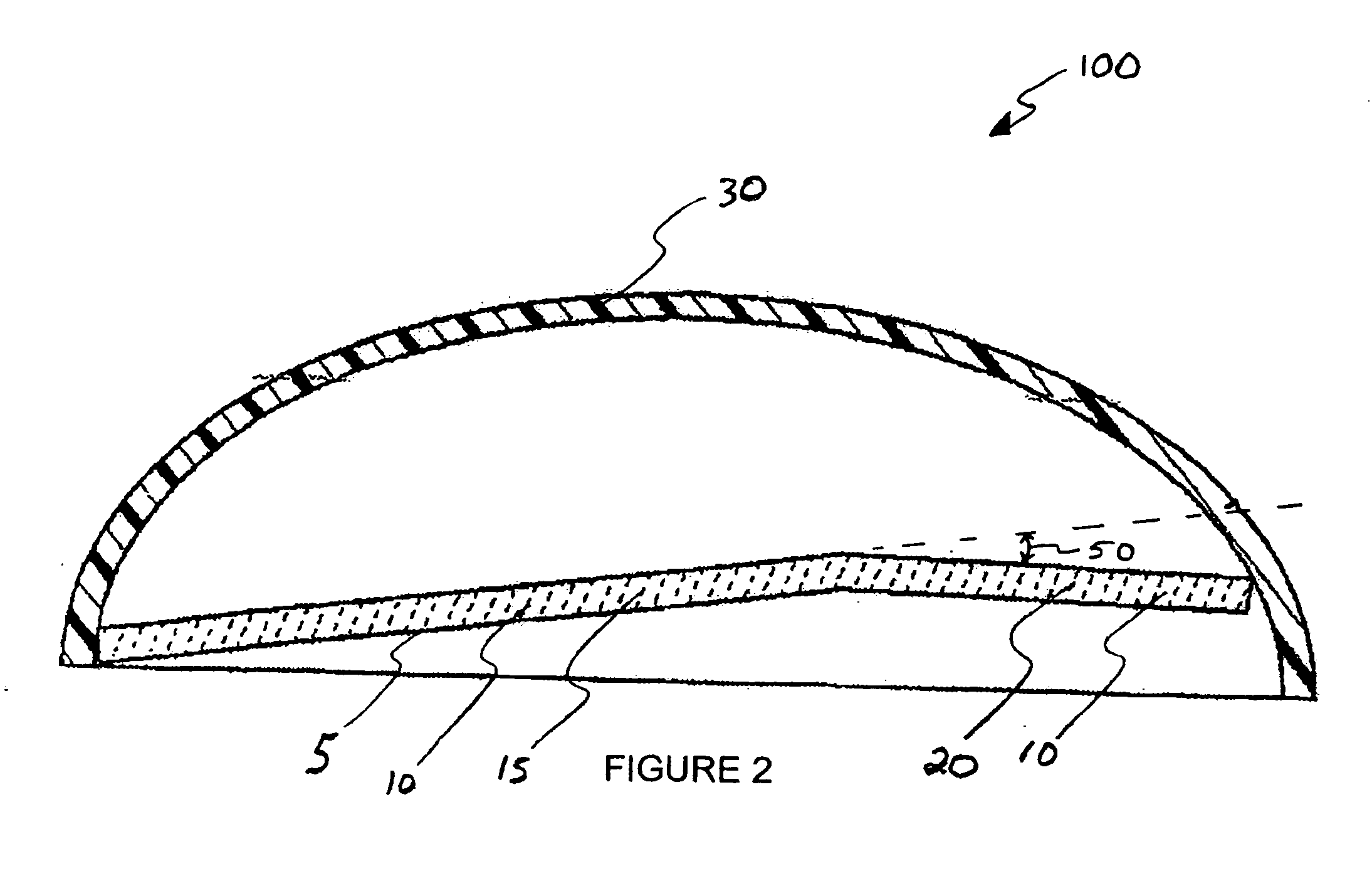
[0018] Now referring to the drawings submitted herewith, wherein the various elements depicted therein are not necessarily drawn to scale and wherein like reference numerals are used for like elements throughout the figures and in particular to FIGS. 1 and 2 there is a rearview mirror system 100 constructed according to the principles of the present invention.

[0019] The rearview mirror system 100 includes a mirror 10 that comprises a reflective surface 5. The reflective surface 5 is manufactured from conventional materials known in the art that allows viewing of objects generally rearward of a vehicle, with the rearview mirror system 100 being secured to the side of the vehicle.

[0020] Mirror 10 includes two sections 15 and 20. Sections 15 and 20 are each configured in a substantially planar manner, and positioned so that section 15 and section 20 are generally configured in a non-parallel planar manner with respect to each other forming an angle 50 there between.

[0021] The inters...


PUM


Abstract

A rearward viewing mirror attached to a vehicle configured to increase the viewing area generally rearward of the vehicle, in particular, the driver's blind spot. The rearward viewing mirror includes a reflective surface configured to provide an image of objects rearward of the vehicle. The reflective surface further includes a first section and a second section that are configured in a non-parallel manner. An intersecting angle between the first section and the second section is formed within the range of nine to thirteen degrees. The second section is positioned proximate the vehicle such that the rearward viewing mirror provides increased viewing of objects proximate the driver's blind spot while inhibiting distortion thereof.

Description

PRIORITY UNDER 35 U.S.C. §119(e) & 37 C.F.R. §1.78 [0001] This nonprovisional application claims priority based upon the following prior United States provisional patent application entitled: Omni-vision mirror, application No. 60 / 690,083, files Jun. 11, 2005, in the name of Gary T. Starbuck, which is hereby incorporated by reference for all purposes.FIELD OF THE INVENTION [0002] The present invention relates to a rearward vision enhancement apparatus, more specifically but not by way of limitation, a side rearview mirror secured to a vehicle, the mirror being designed to substantially decrease the blind spot of the driver. BACKGROUND OF THE INVENTION [0003] Millions of individuals spend time every day driving different types of vehicles to accomplish a multitude of daily tasks. Whether it is an automobile, truck, or motorcycle all of these vehicles are commonly equipped with at least one side rearview mirror to facilitate proper vision behind the vehicle. Proper vision behind the v...

Claims


Application Information

Patent Timeline
IPC IPC(8): G02B5/10
CPCB60R1/08
Inventor STARBUCK, GARY T.
Owner STARBUCK GARY T
Learn More