Rubber track and method of producing core metal for rubber track
a technology of rubber track and core metal, which is applied in the direction of driving belts, belts/chains/gearrings, mechanical equipment, etc., can solve the problems of increasing traveling vibration, metal core inclination, and rolling wheels sinking after all, so as to reduce the shearing area, reduce the cost, and prevent the effect of traveling vibration
- Summary
- Abstract
- Description
- Claims
- Application Information
AI Technical Summary
Benefits of technology
Problems solved by technology
Method used
Image
Examples
example 1
[0066] The present invention is explained in detail with reference to the figures as follows.
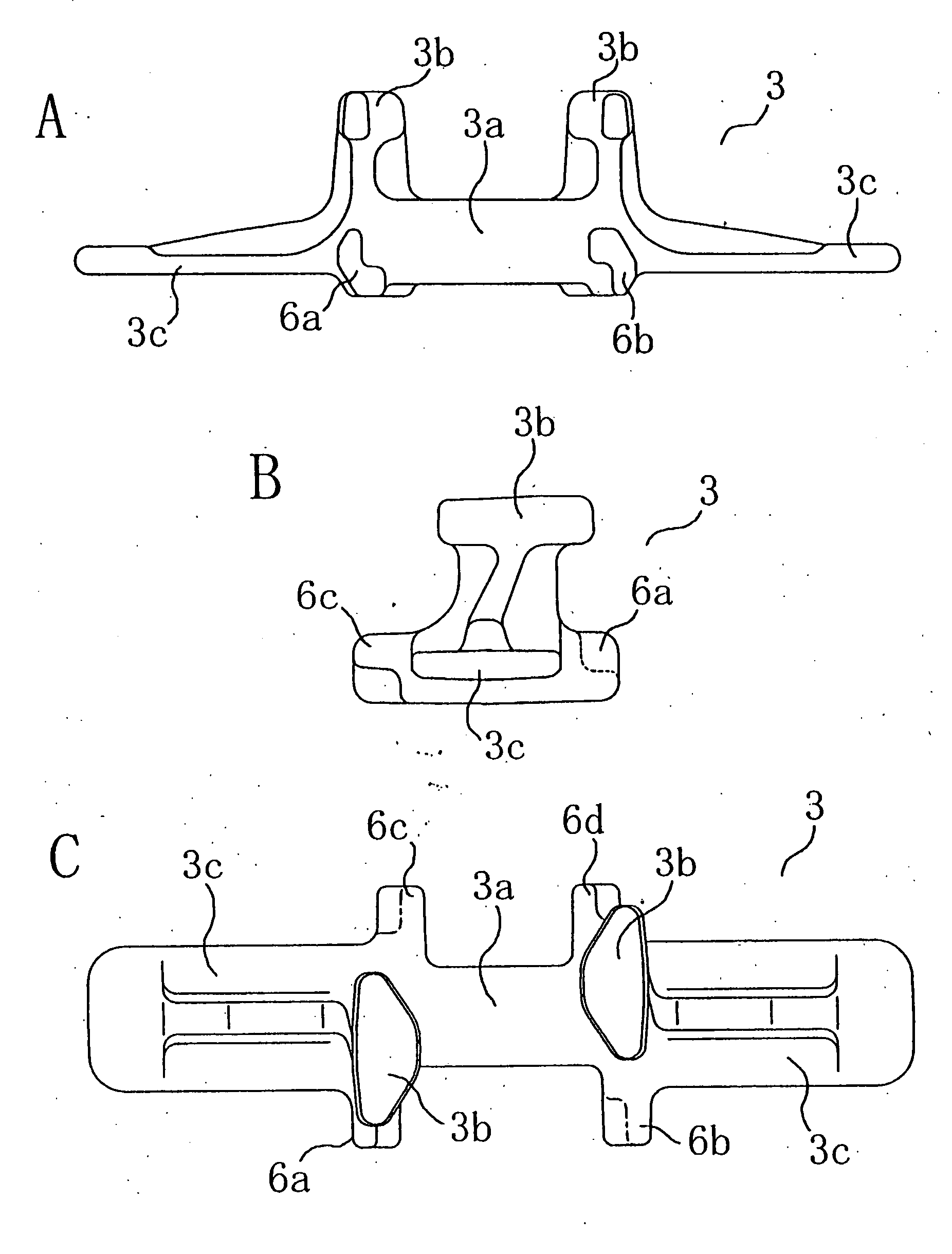
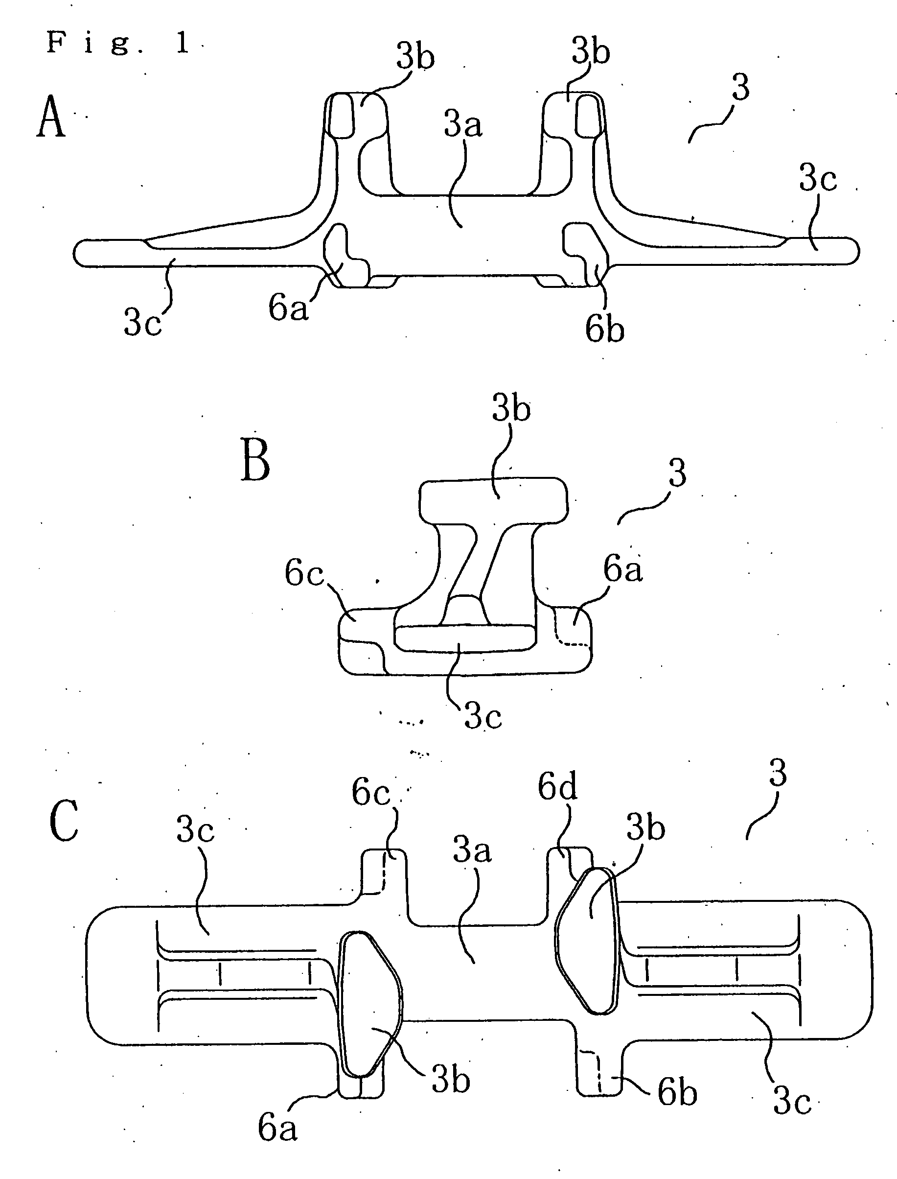
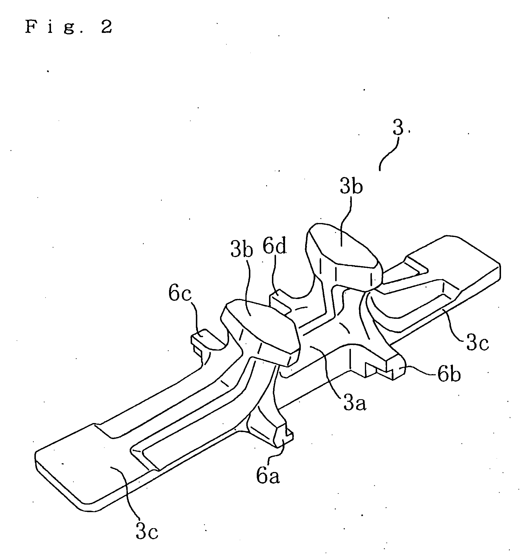
[0067]FIG. 1 shows a metal core 3 to be embedded in a rubber crawler body 2 (FIG. 3B) of a rubber crawler track 1 (FIG. 3A) in the first embodiment. FIG. 1A is a front view; FIG. 1B is a side view; and FIG. 1C is a plan view of a side opposite the tread of the metal core 3 embedded in the rubber crawler track. FIG. 2 is a perspective view of the metal core 3. FIG. 3 shows the rubber crawler track 1 in the first embodiment. FIG. 3A is a plan view of a side opposite the tread; FIG. 3B is a sectional view taken along X-X of FIG. 3A; and FIG. 3C is a side view of FIG. 3A.
[0068] The rubber crawler track 1 comprises the rubber crawler body 2 of an endless belt body formed by a rubber elastic body, metal cores 3, lugs 4 and steel cord 5 rows. The metal cores 3 are embedded in the rubber crawler body 2 at a fixed interval in the crawler circumferential direction. The lugs 4 protrude from the tread...
example 2
[0088]FIG. 9 shows a metal core 3′ embedded in the rubber crawler body of the second embodiment. FIG. 9A is a plan view of the side opposite the tread, and FIG. 9B is a side view.
[0089] The metal core 3′ has a tapered horn portion 7 on an end of the horizontal protrusion of one side in the crawler circumferential direction (metal core width direction). When the metal core 3′ is embedded in the rubber crawler body, the ends of the horizontal protrusions 6′ between adjacent metal cores in the crawler circumferential direction overlap within a fixed length in the crawler width direction and in the crawler thickness directions. In this case, only one of the horizontal protrusions has the horn portion 7.
[0090] The metal core 3′ in FIG. 9 will be explained. The horn portion 7 is provided on the horizontal protrusion 6a′, not on the horizontal protrusion 6c′ on the opposite side in the metal core width direction as shown in FIG. 9A. And, it is not provided on the horizontal protrusion 6b...
PUM
 Abstract
Description
Claims
Application Information
 - R&D
- Intellectual Property
- Life Sciences
- Materials
- Tech Scout
- Unparalleled Data Quality
- Higher Quality Content
- 60% Fewer Hallucinations
Browse by: Latest US Patents, China's latest patents, Technical Efficacy Thesaurus, Application Domain, Technology Topic, Popular Technical Reports.
© 2025 PatSnap. All rights reserved.Legal|Privacy policy|Modern Slavery Act Transparency Statement|Sitemap|About US| Contact US: help@patsnap.com


